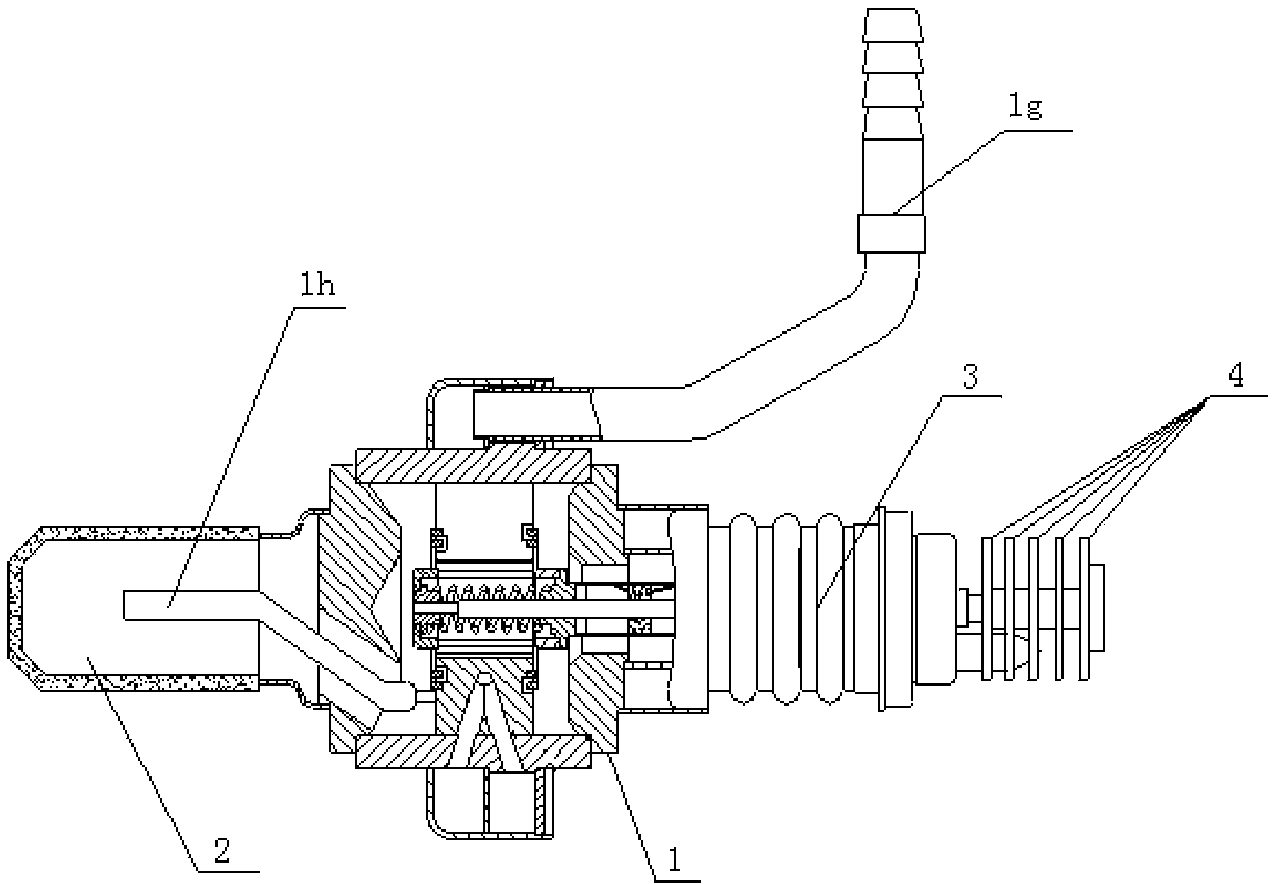
Magnetron with injected locking frequency of 20 kW/2450 MHz

A magnetron and injection lock technology, applied in the field of magnetron, can solve the problems of affecting the working stability and working life of the microwave source, microwave power affecting the heating effect, and it is difficult to eliminate the interference of the magnetron, so as to reduce the low appearance quality factor, optimize the design of the anode structure, and improve the effect of heat dissipation

Inactive Publication Date: 2014-12-24
NANJING SANLE MICROWAVE TECH DEV
View PDF9 Cites 5 Cited by
  • Summary
  • Abstract
  • Description
  • Claims
  • Application Information

AI Technical Summary

Problems solved by technology

The objects to be heated in industrial production are often bulky. Insufficient microwave power will directly affect the heating effect and seriously restrict the production scale, which is far from meeting the needs of large-scale industrial continuous production.
[0003] At present, in the field of microwave heating, the power combining technology uses incoherent power combining, that is, multiple magnetrons are simply used as independent microwave sources for incoherent power combining, which will result in low power combining efficiency and it is difficult to eliminate the gap between the magnetrons. Interference between each other seriously affects the working stability and working life of the microwave source, and even directly damages the microwave source
The reason is that the control accuracy of the frequency of the continuous wave magnetron in the existing technology is not high, so the frequency of the magnetron is discrete, generally at 2450MHz±30MHz, which is far from meeting the requirements of the frequency-locking bandwidth of the injection-locked continuous-wave magnetron. requirements and coherent power combining requirements for continuous wave magnetron frequency, that is, stable operation at 2450MHz

Method used


Image

  • Magnetron with injected locking frequency of 20 kW/2450 MHz
  • Magnetron with injected locking frequency of 20 kW/2450 MHz
  • Magnetron with injected locking frequency of 20 kW/2450 MHz

Examples


Embodiment Construction

[0020] In order to better understand the technical content of the present invention, specific embodiments are given together with the attached drawings for description as follows.

[0021] combine figure 1 and figure 2 As shown, according to a preferred embodiment of the present invention, a 20kW / 2450MHz injection frequency-locked magnetron, a stable power supply 101, a magnetron 102, an excitation cavity 103, an electromagnet 104, a high-stable signal source 105, and four terminals Circulator 106 and absorbing load 110 .

[0022] In the present embodiment, the aforementioned stable power supply 101 is used as a microwave power supply, connected with the magnetron 102, such as figure 2 As shown, the magnetron 102 and the electromagnet 104 are fixed on the excitation chamber 103, and the stabilized power supply 101, the magnetron 102, the electromagnet 103 and the excitation chamber 104 constitute a microwave energy generator for providing microwave power.

[0023] In this...


PUM


Abstract

The invention discloses a magnetron with the injected locking frequency of 20 kW / 2450 MHz. The magnetron comprises a stabilized power supply, a magnetron body, an excitation cavity, an electromagnet, a high-stability signal source, a four-port circulator and an absorbing load. The stabilized power supply is a microwave power supply and is connected with the magnetron body. The magnetron body and the electromagnet are fixed to the excitation cavity. The stabilized power supply, the magnetron body, the electromagnet and the excitation cavity form a microwave energy generator which provides microwave power. The four-port circulator is provided with four ports, the first port is connected with the high-stability signal source, the second port is connected with the excitation cavity, the third port is connected with a load and used for outputting the microwave power to the load, and the fourth port is connected with the absorbing load. The high-stability signal source is used for providing stable 2450 MHz microwave signals, and the 2450 MHz microwave signals are injected into the magnetron body through the four-port circulator. The oscillation frequency of the magnetron body is controlled by the injected signal frequency, and the microwave energy is output through the third port. The magnetron body has the low exterior quality factor.

Description

technical field [0001] The invention relates to the technical field of magnetrons, in particular to a 20kW / 2450MHz injection-locked magnetron. Background technique [0002] In the 2450MHz frequency band, the power of the existing single magnetron can only reach 30kW, and the lifespan is 2000 hours. The output power and lifespan are very limited. The objects to be heated in industrial production are often bulky. Insufficient microwave power will directly affect the heating effect and seriously restrict the production scale, which is far from meeting the needs of large-scale industrial continuous production. [0003] At present, in the field of microwave heating, the power combining technology uses incoherent power combining, that is, multiple magnetrons are simply used as independent microwave sources for incoherent power combining, which will result in low power combining efficiency and it is difficult to eliminate the gap between the magnetrons. Mutual interference serious...

Claims


Application Information

Patent Timeline
Patent Type & Authority Applications(China)
IPC IPC(8): H01J25/50H01J23/00H01J23/36
Inventor 刘友春王荣川白旭斌王法礼吴云龙
Owner NANJING SANLE MICROWAVE TECH DEV
Why Eureka
Try Eureka