
Thermal device and method for increasing temperature of clean boiler smoke obtained by wet desulphurization

A technology of wet desulfurization and thermal devices, applied in separation methods, chemical instruments and methods, separation of dispersed particles, etc., can solve problems such as consumption of high-quality fuel, lack of power for rising airflow, damage to flue and anti-wear materials on the inner wall of chimneys, etc. , to achieve the effect of reducing anticorrosion and maintenance costs, preventing airflow velocity from dropping, and avoiding acid droplet settlement

Active Publication Date: 2014-12-17
SPIC POWER PLANT OPERATION TECH (BEIJING) CO LTD +1
View PDF6 Cites 9 Cited by
  • Summary
  • Abstract
  • Description
  • Claims
  • Application Information

AI Technical Summary

Problems solved by technology

In order to solve this problem, conventional methods use steam to heat the clean flue gas, set up a small oil gun for heating and a flue gas-flue gas heat exchanger (GGH). , leading to corrosion of the heat exchanger and failure; heating with a small oil gun requires the oil gun to be arranged in the clean flue, which not only consumes high-quality fuel, but also corrodes the small oil gun and ignition system with wet flue gas, and the reliability is not high; adopting GGH , using the original flue gas to heat the clean flue gas, due to the small heat transfer temperature difference, the area of ​​the rotary heating surface is large, and the flue gas after desulfurization carries a certain amount of powder such as gypsum, which leads to the blockage of the corrugated plate of the heat exchanger, GGH The running resistance is too large, affecting the normal operation of the unit
[0003] In order to improve the reliability of unit operation, GGH is canceled when designing the desulfurization system of most power plants, and the wet flue gas after desulfurization is directly discharged into the wet chimney. Necessary anti-corrosion measures are taken during design to prevent corrosion of the flue and chimney after desulfurization; In the power plant where GGH has been installed, in order to improve reliability, the GGH was removed, resulting in low-temperature corrosion of the subsequent flue and chimney
At present, the clean flue gas after desulfurization is discharged directly without heating. Regardless of whether the flue and chimney have taken anti-corrosion measures, the acid gas in the wet flue gas will be absorbed when passing through the condensate droplets on the inner wall of the flue and chimney, forming strong acidity. The liquid corrodes and damages the wear-resistant materials on the inner wall of the flue and chimney, causing irreparable damage to the flue and chimney, greatly reducing the operating reliability of the unit, shortening the maintenance cycle of the boiler, anti-corrosion and maintenance costs of the flue and chimney Increase
[0004] In addition, the clean flue gas is discharged directly without heating, resulting in a decrease in the airflow velocity at the chimney outlet, weakening the lifting effect of the wet flue gas through the chimney, and insufficient power for the airflow to rise into the atmosphere, which can easily form gypsum rain and acid droplet settlement around the power plant. The environment around the power plant has suffered a major blow, making it difficult to meet the post-evaluation requirements of the power plant environment

Method used


Image

  • Thermal device and method for increasing temperature of clean boiler smoke obtained by wet desulphurization
  • Thermal device and method for increasing temperature of clean boiler smoke obtained by wet desulphurization
  • Thermal device and method for increasing temperature of clean boiler smoke obtained by wet desulphurization

Examples


Embodiment Construction

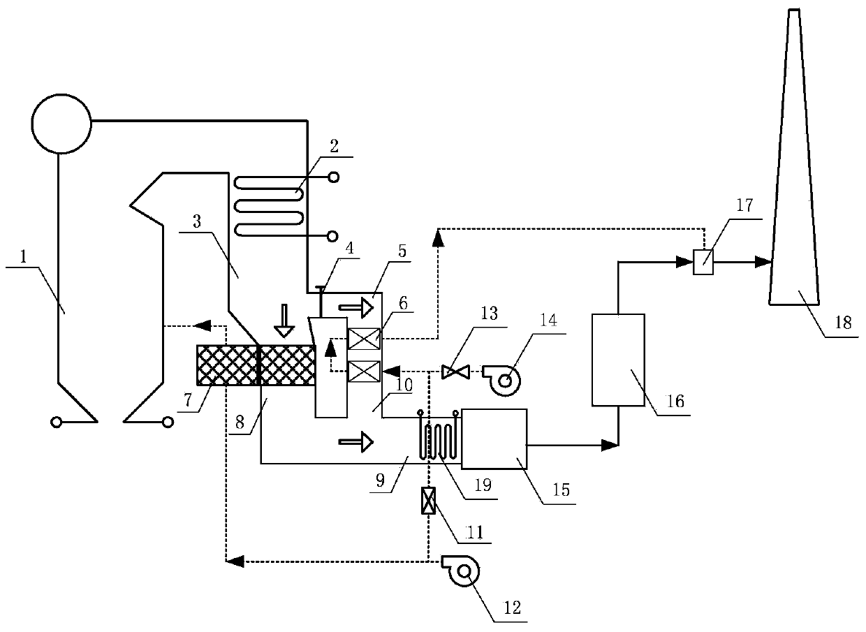
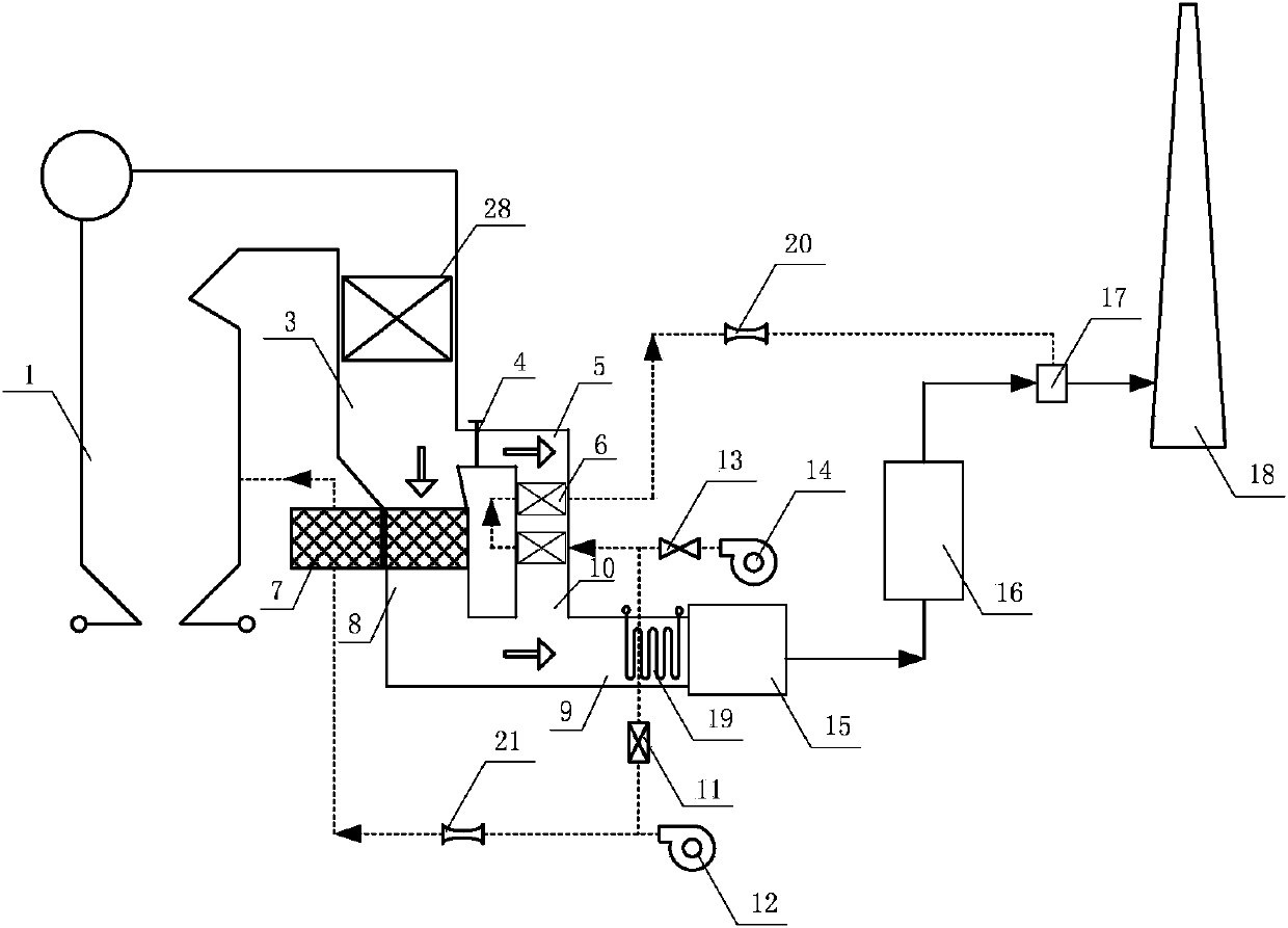
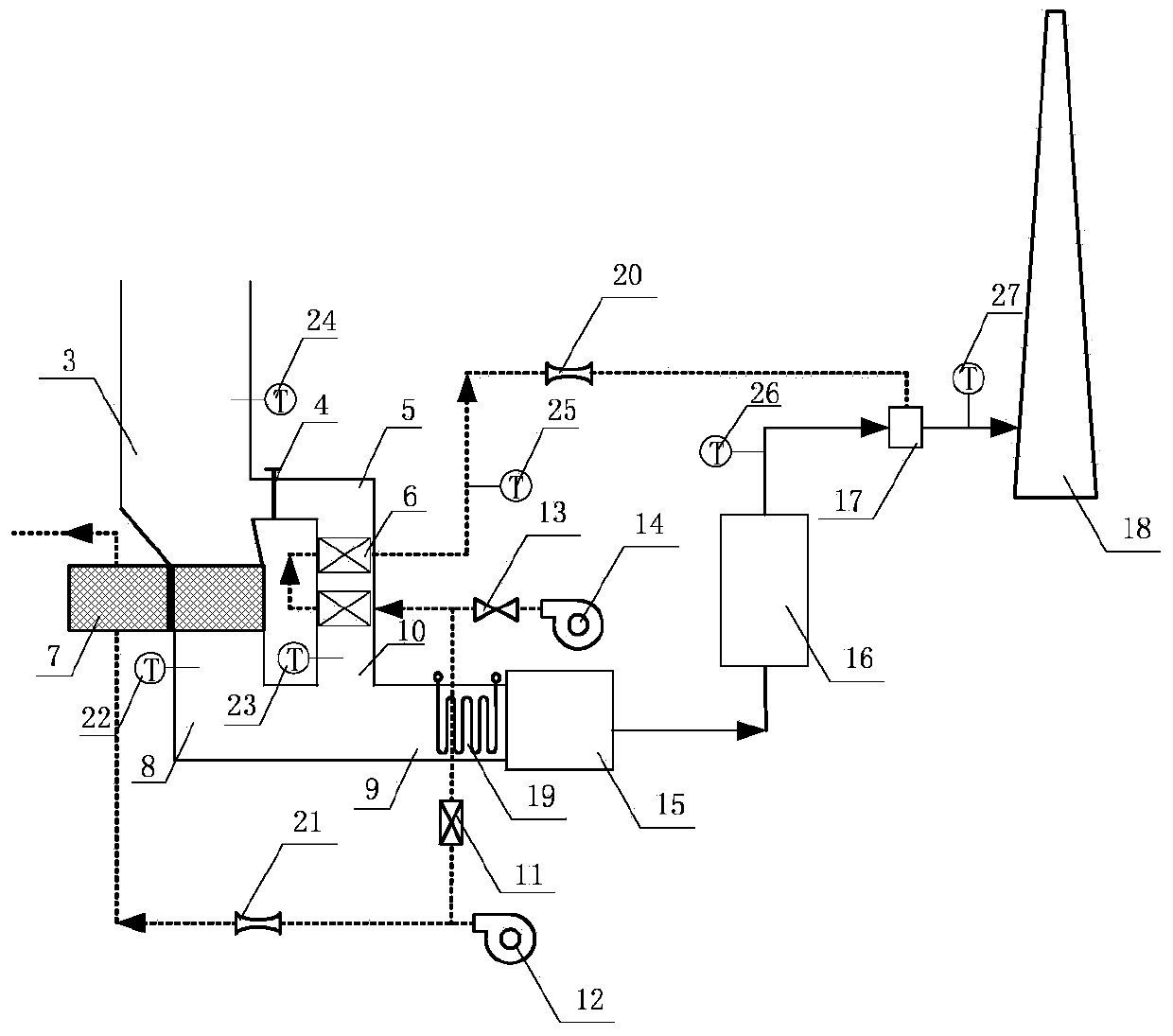
[0039] figure 1 It is a schematic diagram of the thermal device and method (boiler without SCR device) for improving the net flue gas temperature of the present invention; figure 2 It is a schematic diagram of the thermal device and method (boiler with SCR device) for improving the net flue gas temperature of the present invention; image 3 It is a schematic diagram of the thermal measurement and control of the thermal device and method for increasing the net flue gas temperature of the present invention.

[0040] The thermal device for improving the temperature of boiler wet desulfurization net flue gas proposed by the present invention includes: a boiler body, a tail flue gas treatment device and a net flue gas heating device, wherein the tail flue gas treatment device includes a dust collector and a wet desulfurization device, The boiler flue gas passes through the wet desulfurization device to obtain clean flue gas, and the clean flue gas is heated by the clean flue gas ...


PUM


Abstract

The invention discloses a thermal device and method for increasing temperature of clean boiler smoke obtained by wet desulphurization. The thermal device comprises a boiler body, a tail smoke treatment device and a clean smoke heating device, wherein the tail smoke treatment device comprises a dust remover and a wet desulphurization device; clean smoke is obtained after the boiler smoke passes through the wet desulphurization device; the clean smoke is heated by the clean smoke heating device and then discharged into a chimney. The method comprises the following steps: adjusting the amount of smoke entering a bypass smoke channel by virtue of a bypass smoke channel adjusting baffle; heating cold air in an air heater by hot smoke in the bypass smoke channel; feeding the obtained high-temperature hot air into a clean smoke channel behind the wet desulphurization device; mixing the high-temperature hot air with the clean smoke by a mixer; and increasing the mixed smoke temperature to over an acid dew point and discharging the mixed smoke by virtue of the chimney. According to the thermal device and method for increasing temperature of the clean boiler smoke obtained by wet desulphurization, the hot smoke energy is transferred to the clean smoke by taking hot air as a heat medium; the corrosion to the chimney is reduced; the smoke diffusion range is widened so as to prevent gypsum rain from generating at the periphery of a power plant.

Description

technical field [0001] The invention relates to a thermal device and method for increasing the temperature of boiler wet desulfurization net flue gas. Background technique [0002] Installing wet desulfurization devices on coal-fired boilers to purify acid gases in flue gas is a relatively mature technology, which has been widely promoted and applied in thermal power plants. After wet desulfurization, the clean flue gas carries a little water droplets and is in a saturated state , SO3 gas that is not captured by the desulfurization system is easily dissolved in saturated wet flue gas to form sulfuric acid, which corrodes the flue and chimney behind the desulfurization. In order to solve this problem, conventional methods use steam to heat the clean flue gas, set up a small oil gun for heating and a flue gas-flue gas heat exchanger (GGH). , leading to corrosion of the heat exchanger and failure; heating with a small oil gun requires the oil gun to be arranged in the clean fl...

Claims


Application Information

Patent Timeline
IPC IPC(8): B01D53/78B01D53/50
Inventor 袁建丽郑武生李晓民王海民张晓辉李继宏王键张怀宇宿凤明
Owner SPIC POWER PLANT OPERATION TECH (BEIJING) CO LTD
Learn More