Eureka AIR delivers breakthrough ideas for toughest innovation challenges, trusted by R&D personnel around the world.

Dynamic process detection method and fast response circuit of switching power supply

A fast response and circuit technology, applied in the direction of electrical components, adjusting electric variables, output power conversion devices, etc., can solve the problems that affect the output voltage accuracy and the output voltage accuracy is not as good as to achieve fast dynamic response speed and high output voltage accuracy Effect

Active Publication Date: 2014-12-10
MORNSUN GUANGZHOU SCI & TECH
View PDF5 Cites 10 Cited by
  • Summary
  • Abstract
  • Description
  • Claims
  • Application Information

AI Technical Summary

Problems solved by technology

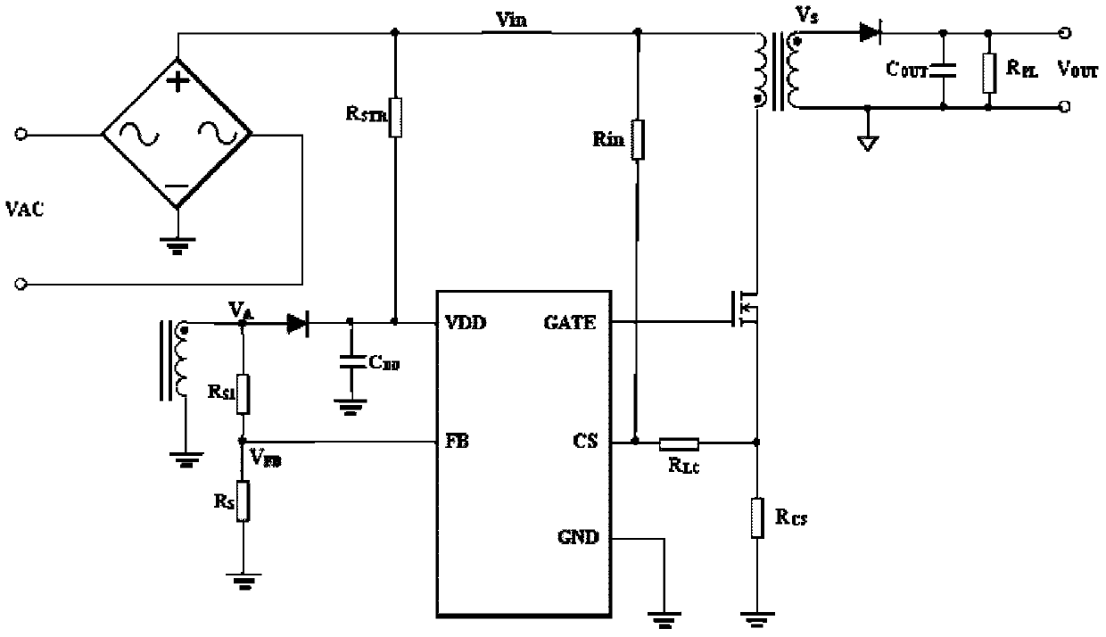
Therefore, the primary-side feedback control with a frequency above 22K audio frequency has a good fast dynamic response. However, the voltage drop of the output diode is different under different currents and temperatures, and its size change directly affects the size of the output voltage. In addition, the transformer turns Number, voltage divider resistor R S and R S1 The accuracy of the output voltage also directly affects the accuracy of the output voltage, so the output voltage accuracy of the primary side feedback control method is far inferior to that of the secondary side control method.

Method used


Image

  • Dynamic process detection method and fast response circuit of switching power supply
  • Dynamic process detection method and fast response circuit of switching power supply
  • Dynamic process detection method and fast response circuit of switching power supply

Examples


Embodiment 1

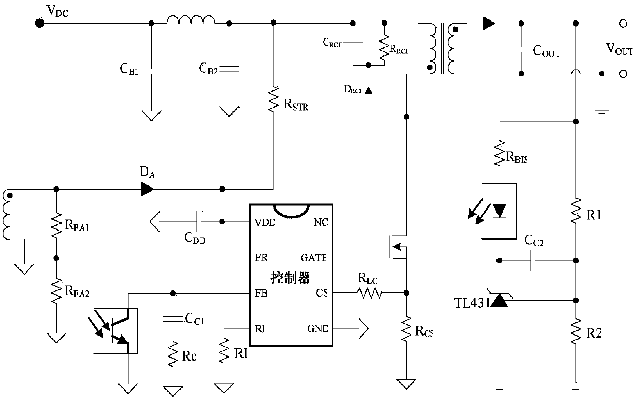
[0032] Figure 4 It is the schematic diagram of the circuit of the first embodiment. A fast response circuit for a switching power supply, comprising: FR terminal of the controller, FB terminal of the controller, CS terminal of the controller, GATE terminal of the controller, output voltage sampling circuit 101, comparison and judgment circuit 102, control signal generation A circuit 103 , a PWM signal generator 104 , and a current generating circuit 105 . The output voltage sampling circuit has two input ports D11 and D14, two output ports D12 and D13, the input port D11 is connected to the FR pin of the controller, the other input port D14 is connected to the GATE pin, and the two output ports D12 and D13 outputs Vo_new and Vo_old signals to two input ports of comparison judgment circuit 102 respectively; Another output port of comparison judgment circuit 102 outputs Vo_fast signal to an input port of control signal generation circuit 103; Another input port of 103 receives...

Embodiment 2

[0046] This embodiment is to propose a dynamic process detection method using the circuit described in Embodiment 1, which is characterized in that:

[0047] The output voltage sampling circuit senses the change of the output voltage by sampling the divided voltage of the auxiliary winding of the transformer (that is, the signal voltage output from the FR pin of the controller), not only sampling and saving the sampling voltage of the current cycle every cycle, but also saving the previous one or several cycles of sampling voltage; the output voltage sampling circuit transmits the current cycle and the sampling voltage of 1 to 4 cycles before the current cycle to the comparison and judgment circuit, and then the comparison and judgment circuit is based on the magnitude of the two voltages To judge whether the output has a dynamic process, if the difference between the sampling voltage ratio of the previous 1 to 4 cycles and the sampling voltage of the current cycle is greater t...


PUM


Abstract

The invention provides a fast response circuit and a dynamic process detection method of a switching power supply. By adopting the fast response circuit and the dynamic process detection method, high output voltage accuracy in a secondary feedback control mode and fast dynamic response speed can be obtained. According to the detection method, the dynamic process when output load changes suddenly can be fast detected, acts can be adopted before secondary voltage negative feedback, output voltage can be adjusted timely, and therefore the dynamic response speed as fast as the primary feedback can be obtained.

Description

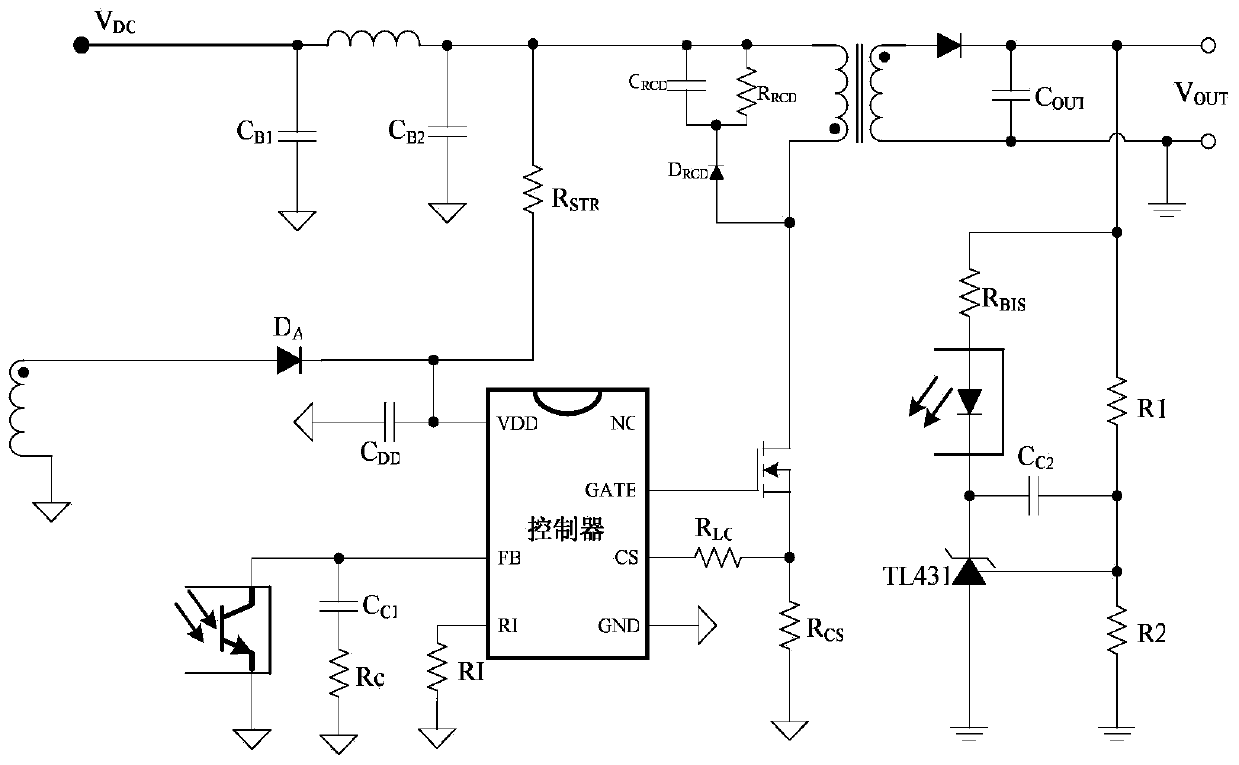
technical field [0001] The invention relates to a dynamic process detection method and a fast response circuit of a switching power supply, in particular to a dynamic process detection method and a fast response circuit of a secondary side feedback switching power supply. Background technique [0002] With the continuous development of switching power supply technology, switching power supply has become the main power supply for electrical appliances, and transformers are used to achieve electrical isolation to improve safety. figure 1 It is a flyback switching power supply commonly used for secondary side feedback control. Resistors R1 and R2 are output voltage sampling resistors. Their divided voltage is used as the input signal of TL431. The signal is amplified by the transconductance amplifier composed of TL431 and optocoupler and then transmitted to Control the FB input terminal of the chip. So the voltage at FB port V FB reflects the power supply output voltage V OU...

Claims


Application Information

Patent Timeline
Patent Type & Authority Applications(China)
IPC IPC(8): H02M3/335
Inventor 唐盛斌
Owner MORNSUN GUANGZHOU SCI & TECH
Why Eureka
Eureka Blog
Learn More