Inductor manufacturing method

A manufacturing method and technology of inductors, applied in the field of inductors, can solve the problems of poor electrical performance and poor heat dissipation effect of inductors, and achieve the effects of good thermal conductivity, good EMI effect and long service life.

Inactive Publication Date: 2014-12-10
POCO HLDG CO LTD
View PDF5 Cites 17 Cited by
  • Summary
  • Abstract
  • Description
  • Claims
  • Application Information

AI Technical Summary

Problems solved by technology

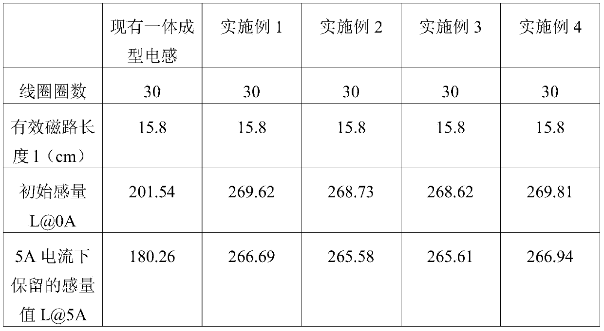
[0013] The invention proposes a method for manufacturing an inductor, which solves the problem of poor electrical performance and poor heat dissipation effect of the inductor in the prior art and solves the damage to the coil caused by mechanical stress in the original integral molding, that is, does not damage or destroy the insulation capacity of the original coil

Method used


Image

  • Inductor manufacturing method

Examples


Embodiment 1

[0037] A method for manufacturing an inductor in this embodiment includes the following steps:

[0038] (1) Through the automatic winding machine, the enameled wire coil is wound into a spiral shape;

[0039] (2) compressing the first ferromagnetic powder into a magnetic core by a powder molding press;

[0040] (3) Put the magnetic core into the hollow cavity of the enameled wire coil;

[0041] (4) the enameled wire coil that magnetic core is housed is packed in the injection mould;

[0042] (5) uniformly stirring the second ferromagnetic powder with the high-temperature resin glue and the binder successively to obtain the feeding material of the mixed powder;

[0043] (6) The mixed powder is granulated and injected into the cavity of the injection mold for sintering to obtain the outer magnet, and the density of the outer magnet is ensured to be lower than the density of the magnetic core.

[0044] (7) Cooling and stripping to obtain a molded inductor.

[0045] (8) A heat...

Embodiment 2

[0049] In this embodiment, the difference from embodiment 1 is that the density of the outer magnet is 5.5g / cm 3 , the core density is 6.0g / cm 3 ; The radiator is made of pure copper material. Other steps in this embodiment are the same as in Embodiment 1.

Embodiment 3

[0051] In this embodiment, the difference from Embodiment 1 is that the density of the external magnet is 5.0 g / cm 3 , the core density is 7.0g / cm 3 . Other steps in this embodiment are the same as in Embodiment 1.


PUM

PropertyMeasurementUnit
densityaaaaaaaaaa
densityaaaaaaaaaa
densityaaaaaaaaaa

Abstract

The invention provides an inductor manufacturing method. The method includes the following steps that first, an enameled wire coil is wound; second, first ferromagnetic powder is pressed into a magnetic core; third, the magnetic core is installed in a hollow cavity of the coil; fourth, the coil is installed in an injection mold; fifth, second ferromagnetic powder and high-temperature resin are evenly stirred and mixed power can be obtained; sixth, the mixed powder is injected into the injection mold and formed so that an outer magnet can be obtained, and it is guaranteed that the density of the outer magnet is smaller than that of the magnetic core; seventh, cooling and demolding are performed so that an inductor can be obtained. The inductor manufactured according to the scheme has the advantages that the inductor is good in thermal conductivity and long in service life; the density of the magnetic core is different from that of the outer magnet, a totally-sealed magnetic shielding structure is achieved as a whole, and the EMI effect of the inductor is better compared with that of an existing integrally formed inductor; the problem that a coil is damaged by mechanical stress in the original integrally formed inductor is solved, and in other words, the insulating capacity of the original coil is not weakened.

Description

technical field [0001] The invention relates to the field of inductors, in particular to an inductor manufacturing method. Background technique [0002] With the development of the electronics industry, filters, choke coils, transformers and reactors are widely used in circuit control systems in various switching power supplies, UPS, photovoltaic inverters, wind energy and other power supplies. Filtering, rectification, and inverter can all be applied to inductive components. [0003] The use of inductors or reactors plays a vital role in the development of the modern electronics industry. The components made by traditional techniques are gradually not fully suitable for the development of miniaturization in the future. To develop a high-performance miniaturized inductor or reactor It is of great significance to adapt to the rapid development of modern electronic technology. [0004] The manufacturing process of traditional inductors or reactors mainly includes: [0005] ...

Claims


Application Information

Patent Timeline
Patent Type & Authority Applications(China)
IPC IPC(8): H01F41/00H01F17/04
Inventor 郭雄志
Owner POCO HLDG CO LTD
Why Eureka
Try Eureka