Base plate conveying device

A transmission device and substrate technology, applied in conveyors, transportation and packaging, non-mechanical conveyors, etc., can solve problems affecting the quality of liquid crystal panels, occupying a large area, and easily scratching substrates, etc., to save equipment costs, Easy cleaning and maintenance, stable transmission process

Inactive Publication Date: 2014-12-03
BOE TECH GRP CO LTD +1
View PDF7 Cites 19 Cited by
  • Summary
  • Abstract
  • Description
  • Claims
  • Application Information

AI Technical Summary

Problems solved by technology

[0004] 1. The glass substrate 30 rotates relative to the roller 10a, which is prone to defects such as scratches;
[0005] 2. If figure 2 As shown, this kind of substrate conveying device is mostly one-way conveying, and it is installed between two adjacent process equipments, occupying a large area of ​​space;
[0006] 3. The roller is driven by the roller, and there is friction between the roller and the roller. For the LCD panel manufacturing industry, particles caused by friction are not allowed, which will affect the quality of the LCD panel
[0008] Magnetic levitation technology uses the principle of "same sex repels each other and opposite sex attracts" to make magnets have the ability to resist gravity and form a certain distance between magnets of the same polarity, so as to realize non-mechanical contact operation, with no wear and pollution , low efficacy, low noise, etc., can reduce the generation of pollution particles, but for large-size glass substrates, the rollers are not supported in the middle of the axial direction. Deformation; and because the contact area between the roller and the substrate is small, there is still the problem that the substrate and the roller slide relative to each other and easily scratch the substrate

Method used


Image

  • Base plate conveying device
  • Base plate conveying device
  • Base plate conveying device

Examples


Embodiment Construction

[0032] The principles and features of the present invention are described below in conjunction with the accompanying drawings, and the examples given are only used to explain the present invention, and are not intended to limit the scope of the present invention.

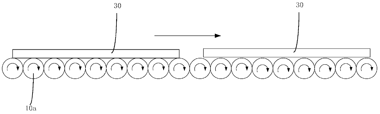
[0033] Aiming at the problem that the substrate conveying device in the prior art adopts the roller conveying method, which is easy to scratch the substrate, and is prone to produce friction dust to affect product quality, the present invention provides a substrate conveying device, which can avoid substrate scratches and reduce friction and dust production occur.

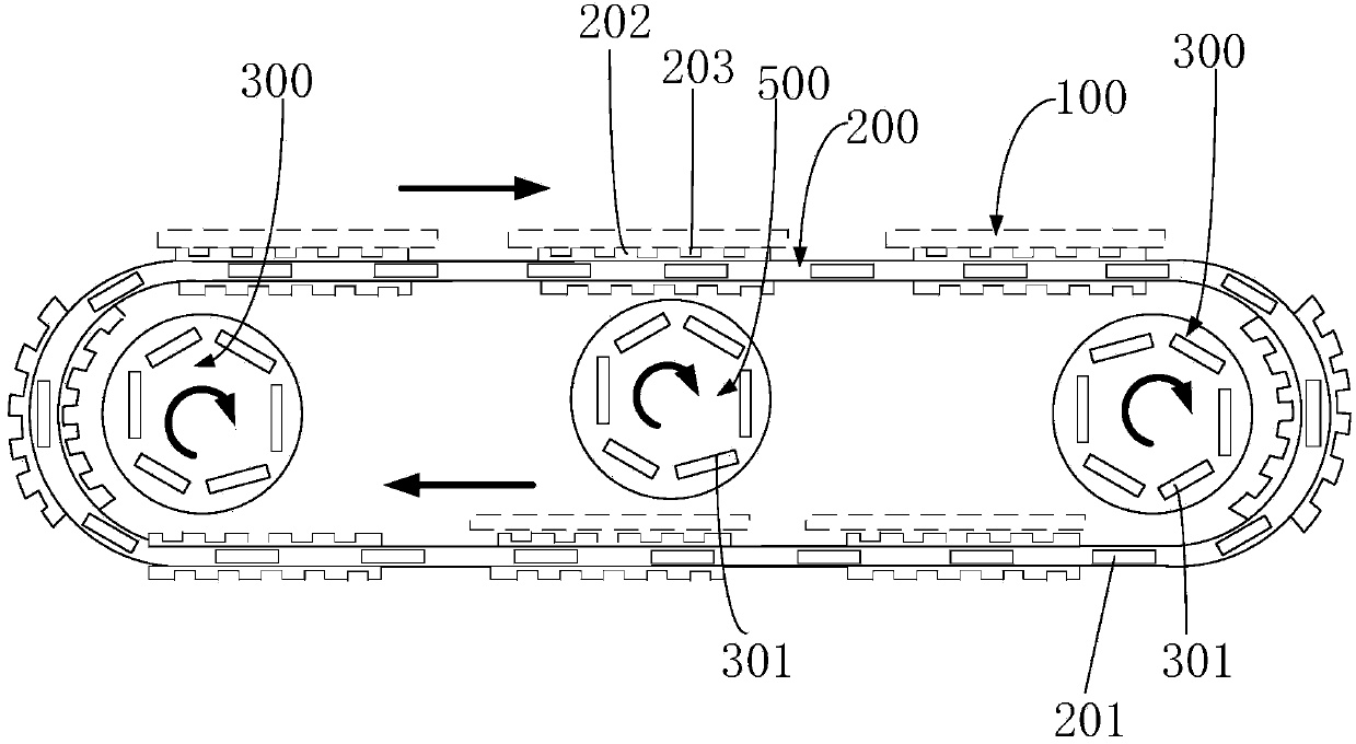
[0034] Such as image 3 with Figure 4 As shown, the substrate transfer device provided by the present invention includes:

[0035] a conveyor belt 200 for carrying the substrate 100;

[0036] At least two maglev driving wheels 300, the conveyor belt 200 is arranged on at least two maglev driving wheels 300;

[0037] Wherein, a plurality of first mag...


PUM


Abstract

The invention provides a base plate conveying device which comprises a conveying belt used for carrying a base plate and at least two magnetic levitation driving wheels, wherein the conveying belt is arranged on the at least two magnetic levitation driving wheels; a plurality of first magnetic blocks are arranged on each of the magnetic levitation driving wheels at intervals along circumferential direction; a plurality of second magnetic blocks opposite to the first magnetic blocks are distributed on the conveying belt at intervals; the opposite surfaces of the first magnetic blocks and the second magnetic blocks are homopolar and are used for generating a magnetic levitation force between the second magnetic blocks and the first magnetic blocks for driving the conveying belt to move between the at least two magnetic levitation driving wheels during a rotating process of the magnetic levitation driving wheels. The base plate conveying device provided by the invention is capable of reducing base plate scratching; no friction particle is generated; the influence on product quality caused by production line dust generation is prevented.

Description

technical field [0001] The invention relates to the technical field of liquid crystal manufacturing, in particular to a substrate conveying device. Background technique [0002] At present, in the liquid crystal panel manufacturing industry, the conveyor belt of the substrate conveying device used to convey the glass substrate is generally formed by arranging many rollers. Such as figure 1 As shown, the glass substrate 30 advances under the driving of the rollers 10a, and enters the rear group of rollers from the front group of rollers. [0003] Traditional substrate conveying devices have the following problems: [0004] 1. The glass substrate 30 rotates relative to the roller 10a, which is prone to defects such as scratches; [0005] 2. If figure 2 As shown, this kind of substrate conveying device is mostly one-way conveying, and it is installed between two adjacent process equipments, occupying a large area of ​​space; [0006] 3. The roller is driven by the roller,...

Claims


Application Information

Patent Timeline
IPC IPC(8): B65G54/00B65G15/42
Inventor 庞立斌高雪松赵杨
Owner BOE TECH GRP CO LTD
Why Eureka
Try Eureka