
Topology detection method based on cloud computing network

A technology of cloud computing network and detection method, which is applied in the direction of data exchange network, digital transmission system, electrical components, etc., and can solve problems such as complex topology, high degree of service level differentiation, and large data flow

Active Publication Date: 2014-11-19
NANJING UNIV OF POSTS & TELECOMM
View PDF2 Cites 12 Cited by
  • Summary
  • Abstract
  • Description
  • Claims
  • Application Information

AI Technical Summary

Problems solved by technology

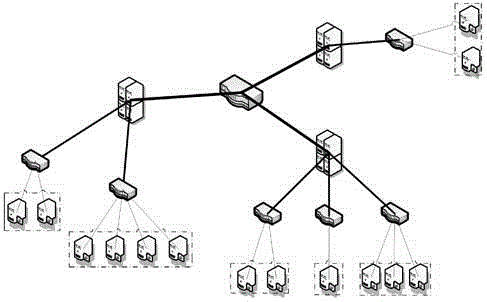
However, the network topology of the backend of the cloud computing system is different from the general network topology characteristics: its server nodes are widely distributed, the data flow is large, the service level is highly differentiated, the scalability and reliability requirements are strong, and the topology structure is relatively complex. There is a need for re-study

Method used


Image

  • Topology detection method based on cloud computing network
  • Topology detection method based on cloud computing network
  • Topology detection method based on cloud computing network

Examples


Embodiment Construction

[0027] 1. Build the Openstack real environment according to the preset topology diagram.

[0028] 2. When performing the first-layer network topology detection, randomly select a virtual machine under each router to number and program it into the corresponding socket program, and use the virtual machine under the router to receive a large data packet and two small data packets respectively. , measure the data delay between each pair of routers and computing nodes, and obtain the time difference of each pair of small data packets. Inferring through the MLT algorithm, (1) choose a random start state s 0 =(T 0 + u 0 ); (2) enter the next state s 1 , to get the minimum value: min { 1 , p ( T 1 , u 1 | x ...


PUM


Abstract

The invention provides a topology detection method based on a cloud computing network. The topology detection method is suitable for detecting a network topology under the environment of the cloud computing network, and is used for detecting the topology from two separate layers, wherein the first layer of the topology comprises a router and a computing node; time delay is detected by sending a socket 'sandwich' pack; the second layer of the topology comprises the distribution of virtual machines under the computing node in the cloud computing environment. The method is used for detecting the communication time delay between the virtual machines with an MPI, and merging and clustering by adopting the disjoint-set data structure algorithm after corresponding calculation, so as to obtain the distribution of the virtual machines. Through the adoption of the method, the integral topological structure under the whole cloud computing network environment can be detected more completely.

Description

technical field [0001] The present invention is applicable to the cloud network environment. Aiming at the characteristics of the cloud environment network, the cloud environment topology is divided into the first layer topology composed of routers and computing nodes and the second layer topology composed of the distribution of virtual machines. structure, and use the corresponding method to detect the topology. Background technique [0002] As the network is more and more closely connected with people's life, network users are also paying more and more attention to the performance characteristics of the network and the degree to which the benefits they get through the network can be guaranteed. On the one hand, the modern network management system is required to develop more perfectly and control the behavior of the network better. On the other hand, it is required to accurately detect and conveniently regulate network performance parameters. To this end, various network...

Claims


Application Information

Patent Timeline
IPC IPC(8): H04L12/751H04L29/08H04L45/02
Inventor 王少辉董从翔肖甫韩志杰王汝传刘佳
Owner NANJING UNIV OF POSTS & TELECOMM
Learn More