Method, device and reactor for recovery of sulfur from acidic gas
A technology for acid gas and sulfur recovery, applied in separation methods, sulfur preparation/purification, chemical instruments and methods, etc., can solve problems such as high toxicity, achieve reliable reaction temperature, simple and reasonable structure, and save equipment space. Effect
- Summary
- Abstract
- Description
- Claims
- Application Information
AI Technical Summary
Problems solved by technology
Method used
Image
Examples
Embodiment 1
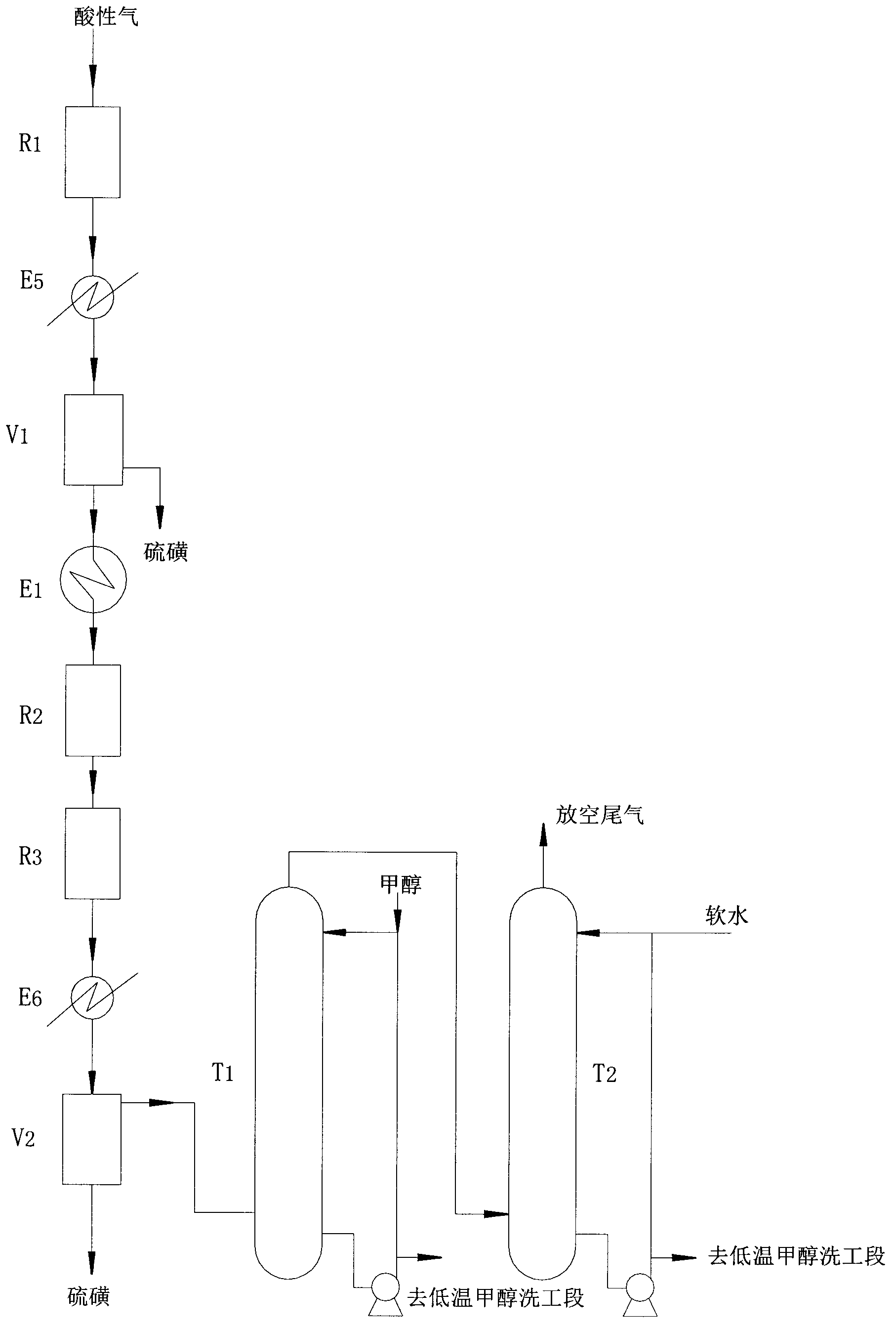
[0066] Use as figure 1 The method of the present invention shown and such as image 3 The device shown performs acid gas desulfurization, and the device includes a first catalytic oxidation reactor R connected in sequence 1 , The first water cooler E 5 , The first sulfur separator V 1 , The first heat exchanger E 1 , Hydrolysis reactor R 2 , The second catalytic oxidation reactor R 3 , The second water cooler E 6 , The second sulfur separator V 2 , Room temperature alcohol washing tower T 1 And tail gas washing tower T 2 , The normal temperature alcohol scrubber T 1 And tail gas washing tower T 2 Each is equipped with a pump.
[0067] The first catalytic oxidation reactor adopts a water-cooled coiled tube reactor, such as the reactor in the applicant's utility model patent application 201220234489.5.
[0068] The gas to be treated is the acid gas from the coke oven gas low-temperature methanol washing section, and its gas volume and composition are as follows:
[0069]
[0070] Press ...
Embodiment 2
[0072] Realize as figure 1 In the process shown, the three steps of primary catalytic oxidation, hydrolysis, and secondary catalytic oxidation can be carried out in the same reactor, ie Figure 4 In the horizontal reactor shown, the inside of the reactor is divided into three reaction chambers with two vertical partitions: hydrolysis reaction chamber R 2a , The first catalytic oxidation reaction chamber R 1a And the second catalytic oxidation reaction chamber R 3a , Where the hydrolysis reaction chamber R 2a Located in the middle, the first catalytic oxidation reaction chamber R 1a And the second catalytic oxidation reaction chamber R 3a Located in the hydrolysis reaction chamber R 2a On both sides, where the first catalytic oxidation reaction chamber R 1a It is a heat exchange water-cooled heat exchange reaction chamber, with heat exchange tubes distributed in the reaction chamber, and the hydrolysis reaction chamber R 2a And the second catalytic oxidation reaction chamber R 3a It...
Embodiment 3
[0077] Another structural form of the reactor of the present invention, such as Image 6 As shown, the inside of the reactor is divided into two left and right reaction chambers by vertical partitions, where the reaction chamber R 1a It is a catalytic oxidation reaction chamber, and the other reaction chamber is hydrolysis reaction chamber R from bottom to top. 2a And the secondary catalytic oxidation reaction chamber R 3a , One of the catalytic oxidation reaction chamber R 1a Water-cooled heat exchange reaction chamber, hydrolysis reaction chamber R 2a Adiabatic reaction chamber, secondary catalytic oxidation reaction chamber R 3a It is an adiabatic reaction chamber. Hydrolysis reaction chamber R 2a And the secondary catalytic oxidation reaction chamber R 3a There is no partition between them, and two upper and lower reaction chambers are formed by filling different catalyst layers used by each.
[0078] The reactor of the above structure can be used as Figure 7 Device shown:
[0...
PUM
 Abstract
Description
Claims
Application Information
 - R&D
- Intellectual Property
- Life Sciences
- Materials
- Tech Scout
- Unparalleled Data Quality
- Higher Quality Content
- 60% Fewer Hallucinations
Browse by: Latest US Patents, China's latest patents, Technical Efficacy Thesaurus, Application Domain, Technology Topic, Popular Technical Reports.
© 2025 PatSnap. All rights reserved.Legal|Privacy policy|Modern Slavery Act Transparency Statement|Sitemap|About US| Contact US: help@patsnap.com


