Eureka AIR delivers breakthrough ideas for toughest innovation challenges, trusted by R&D personnel around the world.

Sphere conveying mechanism of device for machining high-precision sphere

A technology of conveying mechanism and processing equipment, which is applied in the direction of metal processing equipment, grinding machine tools, working carriers, etc., can solve the problems of poor accuracy of processing path control, no ball circulation processing function, and poor processing consistency, so as to achieve convenient observation inspection and guarantee The effect of grinding quality, consistent batch processing

Active Publication Date: 2014-11-05
ZHEJIANG UNIV OF TECH
View PDF5 Cites 4 Cited by
  • Summary
  • Abstract
  • Description
  • Claims
  • Application Information

AI Technical Summary

Problems solved by technology

[0005] In order to overcome the deficiencies of the existing high-precision ceramic ball processing equipment, such as no ball circulation processing function, low processing efficiency, poor processing path control accuracy, and poor processing consistency, the present invention provides a high processing efficiency, processing path The sphere conveying mechanism of the high-precision sphere processing equipment with good control accuracy and good processing consistency

Method used


Image

  • Sphere conveying mechanism of device for machining high-precision sphere
  • Sphere conveying mechanism of device for machining high-precision sphere
  • Sphere conveying mechanism of device for machining high-precision sphere

Examples


Embodiment Construction

[0017] The present invention will be further described below in conjunction with the accompanying drawings.

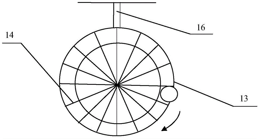
[0018] refer to Figure 1 to Figure 5 , a ball conveying mechanism of high-precision ball processing equipment, including a bracket 16, an upper free raceway 12, a lower free raceway 15, an outer spiral raceway 13, a mandrel and a scraper 14, the upper free raceway 12, The lower free raceway 15 and the outer spiral raceway 13 are installed on the bracket 16, the mandrel is connected with the feeding drive mechanism for driving the mandrel to rotate, and the scrapers are arranged at intervals of circular arcs such as the outer ring of the mandrel. plate 14, the gap between the adjacent scrapers 14 is larger than the ball to be conveyed, the outer spiral raceway 13 is arranged from top to bottom, the outer spiral raceway 13 is attached to the outer surface of the scraper 14, the The gap between adjacent scrapers 14 and the outer spiral raceway 13 form a conveying statio...


PUM


Abstract

The invention discloses a sphere conveying mechanism of a device for machining a high-precision sphere. The sphere conveying mechanism of the device for machining the high-precision sphere comprises a support, an upper free rolling way, a lower free rolling way, an outer spiral rolling way, a mandrel and scrapers, wherein the mandrel is connected with a feeding driving mechanism which is used for driving the mandrel to rotate, the scrapers are arranged on the outer circle of the mandrel at equal arc intervals, the size of a gap between every two adjacent scrapers is larger than that of the sphere to be conveyed, the outer spiral rolling way is arranged from top to bottom and is attached to the outer side faces of the scrapers, a conveyance station used for containing the sphere is formed by the gaps between the adjacent scarpers and the outer spiral rolling way, the upper free rolling way and the lower free rolling way are obliquely arranged, the upper end of the outer spiral rolling way is connected with the upper end of the upper free rolling way, the lower end of the upper free rolling way serves as an outlet of the sphere conveying mechanism, the lower end of the outer spiral rolling way is connected with the lower end of the lower free rolling way, and the upper end of the lower free rolling way serves as an inlet of the sphere conveying mechanism. The sphere conveying mechanism of the device for machining the high-precision sphere has the advantages that circulating machining of the sphere is achieved, the machining efficiency is high, a machining path can be controlled quite accurately, and the machining uniformity is high.

Description

technical field [0001] The invention relates to high-precision sphere processing equipment, in particular to a sphere conveying mechanism. Background technique [0002] High-precision balls are important components in roundness meters, gyroscopes, bearings and precision measurement, and are often used as the benchmark for precision measurement, and play a very important role in precision equipment and precision machining. Especially in ball bearings, it is a key part of ball bearings. The accuracy of bearing balls (spherical deviation, ball diameter variation and surface roughness) directly affects the technical indicators of ball bearings such as motion accuracy, noise and life. Affect the performance of equipment and instruments. Compared with the traditional bearing steel ball material (GCr15), advanced ceramic materials such as silicon nitride have wear resistance, high temperature resistance, corrosion resistance, non-magnetism, low density (about 40% of bearing steel)...

Claims


Application Information

Patent Timeline
Patent Type & Authority Applications(China)
IPC IPC(8): B24B37/025B24B37/27B24B37/34
CPCB24B37/025B24B37/345
Inventor 赵萍傅宣琪袁巨龙周芬芬吕冰海李帆郭伟刚
Owner ZHEJIANG UNIV OF TECH
Why Eureka
Eureka Blog
Learn More