Reinforced earth connection device

A connecting device and reinforced soil technology, which is applied in the fields of soil protection, construction, and infrastructure engineering, etc., can solve the problems affecting the force of geotechnical belts, failure to connect, labor-intensive, etc., achieve significant social and economic benefits, and are simple to manufacture and install , Promote the effect of promotion and application

Inactive Publication Date: 2014-10-15
唐善祥
View PDF6 Cites 0 Cited by
  • Summary
  • Abstract
  • Description
  • Claims
  • Application Information

AI Technical Summary

Problems solved by technology

Since the spacing between the reserved holes in the panel or the reserved steel bar pull rings is generally 50cm, and the width of each geotechnical belt is 3cm, the geotechnical belts passing through the reserved holes in the panel are distributed in a fan shape, and there are inevitably a large number of overlapping and intersecting geotechnical belts. Disadvantages, affecting the force of the geotechnical belt
In the design, a geotechnical belt bypasses the reserved hole or the steel bar pull ring and then turns back to bear the force according to the two ribs, while at the bend of the reserved hole is the force of a geotechnical belt, which reduces the tensile safety factor of the geotechnical belt 50% off, leaving a security risk
The ideal arrangement of geotechnical belts is equidistant parallel distribution, and the force state of the geotechnical belts at the reserved holes or the bends of steel bar pull rings is consistent with the design, and the existing technology cannot meet the above requirements
[0003] In the existing reinforced soil technology, when geogrids are used instead of geotechnical belts as tension bars, the connection between geogrids and panels has become a major difficulty. It is 1-6m wide, and cannot pass through the reserved hole 6-10cm wide, and cannot be connected
The grid is often laid in layers, and after the entire reinforced body is completed, stone masonry or cast-in-place concrete panels are made on the outside of the reinforcement, which is labor-intensive, time-consuming, and expensive.

Method used


Image

  • Reinforced earth connection device
  • Reinforced earth connection device
  • Reinforced earth connection device

Examples


Embodiment Construction

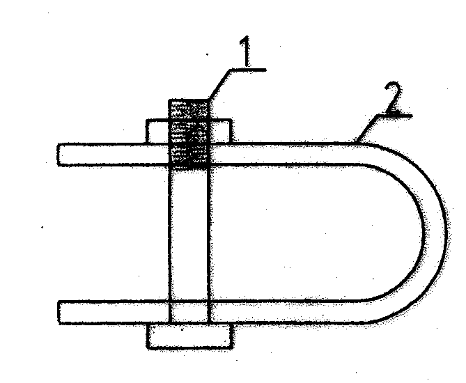
[0030] figure 1 In the shown embodiment, it is a U-shaped plate type reinforced soil connecting device. Fixing bolt 1, arc-shaped plate connection plate 2.

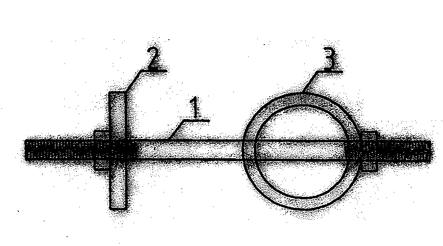
[0031] exist Figure 4 In the shown embodiment, it is a V-bolt reinforced soil connection device. V-shaped connecting bolt 1, upper and lower bolt connecting plate 2.

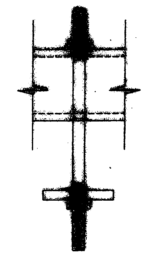
[0032] exist Figure 10 In the embodiment, it is an in-line bolt reinforced soil connection device. One-shaped connecting bolt 1, one end is connected and fixed with the panel. The bolt backing plate 2, the other end is a galvanized steel pipe 3. The geotechnical belt or geogrid is wrapped around the galvanized steel pipe and laid flat on the filler, which completes the connection with the panel.


PUM


Abstract

The invention relates to a reinforced earth connection device which is used for connecting a reinforced earth panel and a geo-belt/geo-grid. According to a novel connection method, the reinforced earth connection device can be V-shaped, U-shaped, circular or the like; the fabrication process is simple, the use is convenient, and the problem that the reinforced earth panel and the grid are difficultly connected is solved; the condition that the existing geo-belts are of flat distribution is changed, geo-belts are of equidistant parallel distribution, and the disadvantage that the geo-belts are prone to overlapping cross and the like due to the fan-shaped distribution of the geo-belts is overcome; the condition that the safety factor of the geo-belts reaches design requirements is ensured.

Description

Technical field [0001] The patent of the invention relates to the connection between the reinforced earth engineering panel and the geotechnical belt used in construction engineering, and the connection device between the panel and the geogrid. Background technique: [0002] Panels and geotechnical belts are the main force-bearing components of reinforced soil engineering. In the prior art, the connection method between the geotechnical belt and the panel is: a reserved hole or a pre-embedded steel bar pull ring is set on the inside of the prefabricated concrete panel, and the geotechnical belt is directly bypassed from the reserved hole or the steel bar pull ring. More than 4 geotechnical belts pass through and are fan-shaped distributed on the soil layer. Since the spacing between the reserved holes in the panel or the reserved steel bar pull rings is generally 50cm, and the width of each geotechnical belt is 3cm, the geotechnical belts passing through the reserved holes ...

Claims


Application Information

Patent Timeline
Patent Type & Authority Applications(China)
IPC IPC(8): E02D3/00
Inventor 唐善祥
Owner 唐善祥
Why Eureka
Try Eureka