Circular combs for combing machines

A technology of combing machine and circular comb, which is applied in the field of circular combing of combing machines, can solve the problems of inability to realize precise adjustment convenience and the like

Active Publication Date: 2017-11-24
MASCHINENFABRIK RIETER AG
View PDF12 Cites 0 Cited by
  • Summary
  • Abstract
  • Description
  • Claims
  • Application Information

AI Technical Summary

Problems solved by technology

However, precise adjustment convenience down to the smallest step size cannot be achieved with such bending elements

Method used


Image

  • Circular combs for combing machines
  • Circular combs for combing machines
  • Circular combs for combing machines

Examples


Embodiment Construction

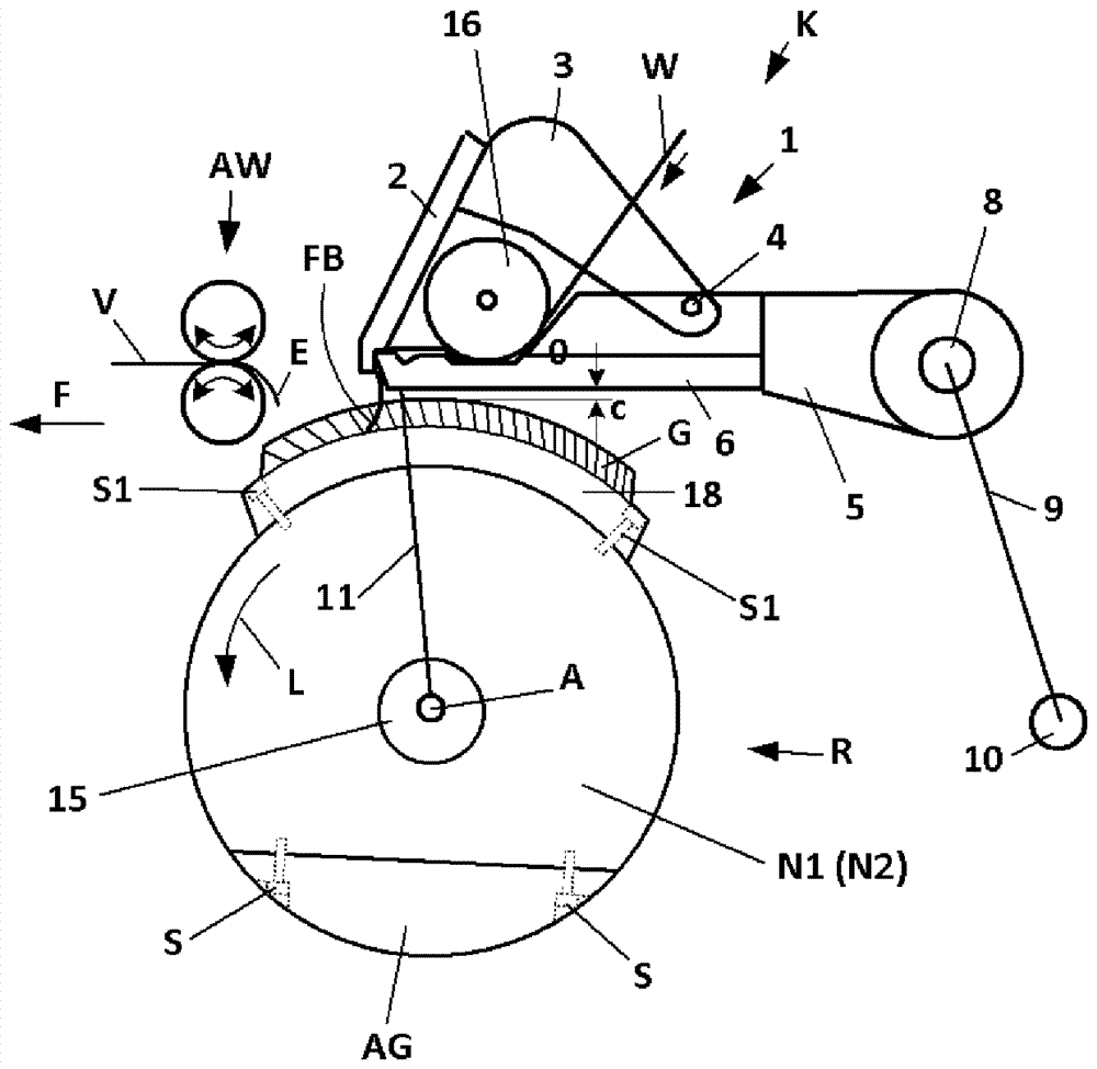
[0040] figure 1 A schematic side view of a combing head K of a combing machine is shown. In known combing machines, for example, eight such combing heads K are arranged side by side. This combing head K, only some of its elements being shown, has a clamp assembly 1 which is mounted in the frame of the combing machine by means of pivoting arms 9, 11 so that said clamp assembly can surround an axis 10 , 15 pivoting reciprocally. Shaft 10 , also called tong shaft, is driven by a drive, not shown in detail, in order to impart a reciprocating movement to tong assembly 1 . The shaft 15 corresponds to the circular comb axis on which the circular comb R is fixed in a fixed rotational relationship. The circular comb shaft 15 with the center axis A is similarly driven continuously or intermittently by a drive not shown. In the known solution shown, the circular comb R fixed on the circular comb shaft 15 below the clamp assembly 1 consists of two hubs N1 permanently fixed on the circ...


PUM


Abstract

The present invention relates to a circular comb of a comber. The circular comb has a base body formed from a hollow profile with a card clothing on an outer circular arc section and is fixed to the shaft in a fixed rotational relationship, wherein, when viewed in the radial direction of the shaft, the mass balance The elements are fixed on the side of the shaft opposite the card clothing. The object of the present invention is to improve the known designs and to ensure easy adjustment of the enveloping radius of the card clothing. For this purpose, it is proposed that the base body is provided with an inner section projecting towards the shaft, which inner section has a depression that is open in the direction of the shaft and extends in the longitudinal direction of the hollow profile, and accommodates a support element in the depression, the supporting element It is supported on the underside of the depression by means of the first support surface on the one hand and on the outer circumference of the shaft by means of the second support surface on the other hand, and fixing means are provided, with which the base body is perpendicular to the base via the support element and the mass balance element. The longitudinal directions of the shafts are clamped against each other.

Description

technical field [0001] The invention relates to a circular comb for a combing machine having a base body formed of a hollow profile with a combing clothing on an outer circular arc section and fixed to a shaft in fixed rotational relation, Therein, a mass balancing element is fixed on the side of the shaft opposite to the combing clothing when viewed in the radial direction of the shaft. Background technique [0002] Circular combs of this type are used in combing machines to comb out existing fiber masses (cotton, wool, etc.), where the fiber masses can be presented as sheets of batting (referred to as laps for short) wound on sleeves. form or in the form of individual fiber strips. The combing cycle rate (combing cycles / minute) has been greatly increased in recent years, which is also accompanied by an increase in productivity. [0003] The demands on such circular combs also increase, for example if the circular combs no longer have a continuous rotational speed, but ar...

Claims


Application Information

Patent Timeline
Patent Type & Authority Patents(China)
IPC IPC(8): D01G19/10
CPCD01G19/105F16D1/087
Inventor P.雅克S.S.汉娜T.汉斯
Owner MASCHINENFABRIK RIETER AG
Why Eureka
Try Eureka