Housing part for a measurement device having a microwave-permeable glass or ceramic window

a technology of microwave-permeable glass or ceramics and housing parts, which is applied in the direction of liquid/fluent solid measurement, instruments, machines/engines, etc., to achieve the effect of simple and cost-effectiv

Active Publication Date: 2019-12-03
SIEMENS AG
View PDF14 Cites 0 Cited by
  • Summary
  • Abstract
  • Description
  • Claims
  • Application Information

AI Technical Summary

Benefits of technology

[0015]It is an object of the invention to provide an attachment of a glass or ceramic window in a housing part of a measurement device, in particular a radar level transmitter, which attachment is pressure-resistant and stable against temperature changes and permits a hermetically sealed separation between the areas on both sides of the window, with the window being mounted in a simple and cost-effective yet secure manner.
[0027]Thus, in order to simplify the configuration to improve manufacturing logistics and to reduce the parts cost, the glass or ceramic window is directly fused into the hole provided in the base wall of the housing part. In addition, there are certain explosion-proof requirements that do not allow the use of threads or clamps to create a boundary between areas with different probability of occurrence of explosive atmospheres, such as areas classified as Zone 1 and Zone according to International Electromechanical Commission (IEC) or division 1 and division 2 according to National Electrical Code (NEC). In this case, a window that is directly fused into the enclosure both avoids the needs for threads or clamps and allows the device to form a boundary between, e.g., a Zone 1 area and a Zone 2 area. When cooled down from the fusing temperature, the circular center portion of the base wall will exert a compressive preload to the window allowing it to withstand various loading conditions during operation. However, in this case of direct glass or ceramic fusion into a metal housing part, the resulting internal stress inside the assembly after fusion is more complex. Depending on the thermal properties of the different materials (glass and metal) and due to non-uniform contraction of the housing part when using the measurement device in, e.g., industrial environments, a bending stress may be created on the window, where the bending stress reduces or even eliminates the compressive preload to the window. In accordance with the invention, the annular zone of reduced wall thickness on both upper and lower surfaces of the base wall effectively and efficiently decouples such bending loading of the housing part from the glass or ceramic window to preserve the precompression stress on the surface of the window.
[0028]The dimension of the zone of reduced wall thickness can be tailored to maximize the decoupling effect for a given load handing requirement of the window and improve the robustness of the configuration. The circular center portion of the base wall advantageously projects above and below the surrounding annular zone of reduced wall thickness, which allows for easier and more precise machining of the outside diameter of the circular center portion, its upper and lower surfaces and the inside diameter of the circular hole. This is particularly important as the window serves as a lead-through for optical or microwave signals, such as in a radar level transmitter. Microwave guides and dielectric matching elements are provided on both sides of the microwave window to propagate microwaves between the desired points, such as a radar antenna and the radar electronics. A precise radial alignment of the waveguides and matching elements to the microwave window on both sides is very critical to good microwave transmission. The outside diameter of the circular center portion and the inside diameter of the hole for the window may be machined in the same set up and prior to glass fusing to achieve the required concentricity between these features. This allows the waveguides to be press-fitted to the circular center portion for alignment with no clearance or dimensional stack up. The dielectric matching elements may be accurately located and held in place by the respective waveguides on assembly. In this arrangement, the matching elements not only adjust the impedance of the microwave window to the impedances of the microwave guides but also place additional compression stress on the surfaces of the window, which are preferably ground flat to be flush with those of the center portion.

Problems solved by technology

Measurement devices are often installed in explosion-hazard environments or are mounted to plant components, such as vessels or pipework, with high pressure and temperature inside.

Method used


Image

  • Housing part for a measurement device having a microwave-permeable glass or ceramic window

Examples


Embodiment Construction

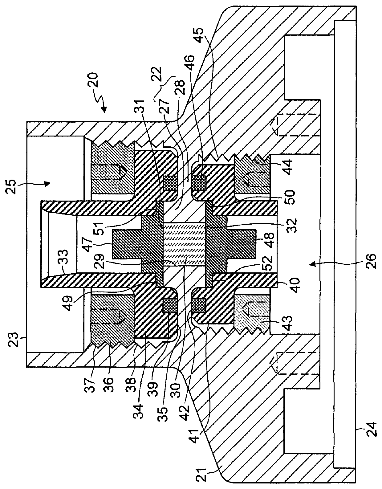
[0032]The housing part comprises a one-piece single metal body 20 of axial symmetry that has an outer circumferential side wall 21 with varying outer diameter and wall thickness and an inner disc-shaped base wall 22. The side wall 21 provides, at an upper end 23, a connection facility for welding or otherwise fastening an electronics housing portion (not shown), and, at a lower end 24, a coupling interface structure for connecting an antenna, such as a horn antenna (not shown).

[0033]The base wall 22 is situated more or less in the middle between the upper end 23 and the lower end 24, thus defining, together with the side wall 21, an upper partially enclosed area 25 and a lower partially enclosed area 26. The base wall 22 comprises a flat circular center portion 27 that projects above and below a surrounding annular zone 28 of reduced wall thickness. Additionally, a pair of annular grooves may be recessed in the annular zone 28, where this is connected to the center portion 27. The c...


PUM


Abstract

A housing part for a measurement device includes a single metal body having an outer circumferential side wall with an upper end and a lower end and an inner disc-shaped base wall located between the upper and lower ends, wherein the side wall and the base wall define two partially enclosed areas, where the base wall comprises a central hole into which a microwave-permeable glass or ceramic window is fused, microwave guides and dielectric matching elements are provided on both sides of the microwave-permeable or ceramic window to propagate microwaves between the desired points such as a radar antenna and radar electronics, and where the matching elements not only adjust the impedance of the microwave window to the impedances of the microwave guides but also put additional compression stress on the surfaces of the fused window, which are preferably ground flat to be flush with those of the center portion.

Description

BACKGROUND OF THE INVENTION[0001]1. Field of the Invention[0002]The invention relates to a housing part for a measurement device having a microwave-permeable glass or ceramic window.[0003]2. Description of the Related Art[0004]Measurement devices are often installed in explosion-hazard environments or are mounted to plant components, such as vessels or pipework, with high pressure and temperature inside. The housing of such measurement devices may be equipped with a glass or ceramic window for observation purposes or as a lead-through for optical or microwave signals out of the housing into the environment or plant component and / or vice versa. In order to withstand the pressure from inside the plant component or resulting from an explosion within the housing, the window is hermetically sealed to the part of the housing in which it is disposed. Depending on requirements, the housing may be hermetically sealed, pressure-resistant or explosion-proof.[0005]U.S. Pat. No. 4,961,628 disclo...

Claims


Application Information

Patent Timeline
Patent Type & Authority Patents(United States)
IPC IPC(8): H05K5/04G01F23/284G01S7/02H01P1/08H01Q1/22
CPCG01F23/284H05K5/04H01Q1/225H01P1/08G01S2007/027G01S7/027
Inventor DUIVENVOORDEN, JOHANNES THEODORUS CORNELISTRAN-NGOC, TRUC
Owner SIEMENS AG
Why Eureka
Try Eureka