
Inverter parallel control method based on controllable virtual impedance

A technology of virtual impedance and control method, applied in output power conversion devices, single-grid parallel feeding arrangements, electrical components, etc., can solve the problems of increasing voltage waveform distortion, affecting the quality of output voltage and power, and reducing circulating current. , easy expansion, good reliability

Active Publication Date: 2014-10-08
SHANGHAI UNIVERSITY OF ELECTRIC POWER
View PDF3 Cites 20 Cited by
  • Summary
  • Abstract
  • Description
  • Claims
  • Application Information

AI Technical Summary

Problems solved by technology

The advantage of this method is that there is no interconnection control, and the control is simple and easy to implement; the disadvantage is that the coupling of active and reactive power will directly affect the control effect. At the same time, since the control target of the droop control is the amplitude and frequency of the reference voltage, That is to say, it achieves current sharing by sacrificing the accuracy of the amplitude and frequency of the inverter, which will affect the power quality of the output voltage
Adding virtual impedance on the basis of traditional droop can reduce circulating current and weaken power coupling without increasing hardware investment, but purely inductive virtual impedance will increase the distortion of voltage waveform under nonlinear load

Method used


Image

  • Inverter parallel control method based on controllable virtual impedance
  • Inverter parallel control method based on controllable virtual impedance
  • Inverter parallel control method based on controllable virtual impedance

Examples


Embodiment Construction

[0039] The present invention will be described in detail below in conjunction with the accompanying drawings and specific embodiments. This embodiment is carried out on the premise of the technical solution of the present invention, and detailed implementation and specific operation process are given, but the protection scope of the present invention is not limited to the following embodiments.

[0040] Such as figure 1 As shown, taking two inverters connected in parallel as an example, the parallel inverter model is used for system power analysis, and the inverter is equivalent to a voltage source with internal resistance, U 1 , U 2 is the output line voltage of the inverter, U 0 is the AC parallel bus voltage, R n +jX n = Z n ∠θ n is the sum of the output impedance of the inverter and the connection impedance, is the inverter output voltage phase, θ n For the equivalent output impedance phase, the relationship between the circulating current and the output impedance...


PUM


Abstract

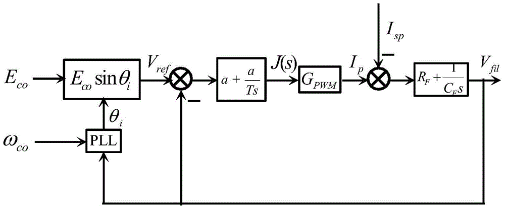
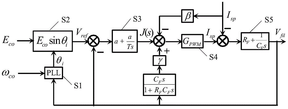
The invention relates to an inverter parallel control method based on controllable virtual impedance. The method comprises the steps that (S1) datum reference frequency omega co and a feedback inverter capacitor voltage Vfil generate a reference voltage amplitude angle theta i through a phase-locked loop module; (S2) a reference voltage Vref is obtained through the reference voltage amplitude angle theta i and a datum reference amplitude Eco; (3) state quantity J(s) is obtained after the feedback inverter capacitor voltage Vfil is subtracted from the reference voltage Vref through a PI controller; (S4) after an output current feedforward value beta Isp is subtracted from the state quantity J(s), feedback compensation is carried out through the inverter capacitor voltage, and a current Ip is then obtained through a P controller; (S5) after an output current Isp is subtracted from the current Ip, the inverter capacitor voltage Vfil is obtained through a filter controller; (S6) equivalent virtual impedance Z0 is obtained, output impedance is adjusted according to a formula, and output currents of multiple parallel inverters are made to be balanced. Compared with the prior art, the output impedance of the inverters is accurate and controllable, and balanced operation of the inverters of a parallel system is achieved.

Description

technical field [0001] The invention relates to a control method for parallel operation of inverters, in particular to an inverter parallel control method based on controllable virtual impedance. Background technique [0002] As new energy power generation is more and more applied to modern power supply systems, more and more distributed inverters appear in low-voltage distribution networks. Several or even dozens of distributed inverters may be connected to an AC line. Since the internal parameters of the inverters cannot be exactly the same, the inverters may run in an unbalanced state, which makes some inverters connected to an AC line lightly loaded and another part of the inverters heavily loaded. Long-term existence will lead to a reduction in the life of the inverter, so it is very important to control the current of the inverter operation for distributed energy generation. At present, the current sharing control of parallel inverters is mainly based on the droop con...

Claims


Application Information

Patent Timeline
Patent Type & Authority Applications(China)
IPC IPC(8): H02J3/38H02M1/12
Inventor 赵晋斌刘海先沈樱
Owner SHANGHAI UNIVERSITY OF ELECTRIC POWER
Learn More