
A Method of Relative Radiation Correction for Staring Satellite Array CCD Camera

A technology of relative radiometric correction and relative radiometric calibration, applied in color TV parts, TV system parts, TV and other directions, can solve dark current noise, shot noise readout noise, quantization noise inconsistency, space and Due to the large influence of detector coupling and the distortion of remote sensing image data, it can achieve the effect of strong universality, taking into account imaging characteristics and practicability, and improving accuracy.

Active Publication Date: 2017-04-05
CHINA CENT FOR RESOURCES SATELLITE DATA & APPL
View PDF5 Cites 0 Cited by
  • Summary
  • Abstract
  • Description
  • Claims
  • Application Information

AI Technical Summary

Problems solved by technology

[0003] With the improvement of the sensitivity and resolution of the staring satellite array CCD camera, the continuous and high-precision ground object spatial information, radiation information and spectral information obtained by it will have a very wide application field; The receiving array is greatly affected by space and probe coupling, not only the dark current noise, shot noise, readout noise, quantization noise, etc. The responsivity of each detector is not consistent, so that when the camera is imaging the same ground object, the digital DN value output by the area array CCD camera is different, that is, the obtained remote sensing image data is distorted; The original remote sensing image data obtained by the array CCD camera is normalized relative radiation correction, and the output values ​​of each detector of the area array CCD camera are adjusted to the same reference so that each detector has the same digital DN output value for the exact same ground features
At present, there is a relatively mature method for the relative radiation correction method of the sun-synchronous satellite linear array CCD camera in orbit, but for the relative radiation correction method of the staring satellite area CCD camera, there is no available literature so far The correction method for this aspect in

Method used


Image

  • A Method of Relative Radiation Correction for Staring Satellite Array CCD Camera
  • A Method of Relative Radiation Correction for Staring Satellite Array CCD Camera
  • A Method of Relative Radiation Correction for Staring Satellite Array CCD Camera

Examples


Embodiment Construction

[0031] (1) Establishment of the radiation response model of the probe: according to the imaging principle of the staring satellite area array CCD camera, fully considering the noise source of the imaging link, the radiation response model of the area array CCD camera probe is established;

[0032] DN(i,j)={f[L(i,j)]+N DC (i,j)+N S (i,j)+N R (i,j)}×G+N Q (i,j) ①

[0033] In the formula: i, j are the detector positions of the area array CCD camera (i∈[1,K], j∈[1,L]);

[0034] DN(i,j) is the digital DN value of detector (i,j);

[0035] f[L(i,j)] is the radiance L(i,j) function received by the detector (i,j);

[0036] N DC (i, j) is the dark current noise of probe (i, j);

[0037] N S (i, j) is the shot noise of probe (i, j);

[0038] N R (i, j) is the readout noise of probe (i, j);

[0039] G is the integrated gain of circuit output;

[0040] N Q (i, j) is the quantization noise of detector (i, j).

[0041] Simplify ① into ②:

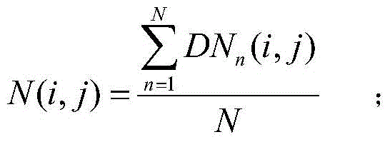
[0042] DN(i,j)=f G [L(i,j)]+N(i,j)② ...


PUM


Abstract

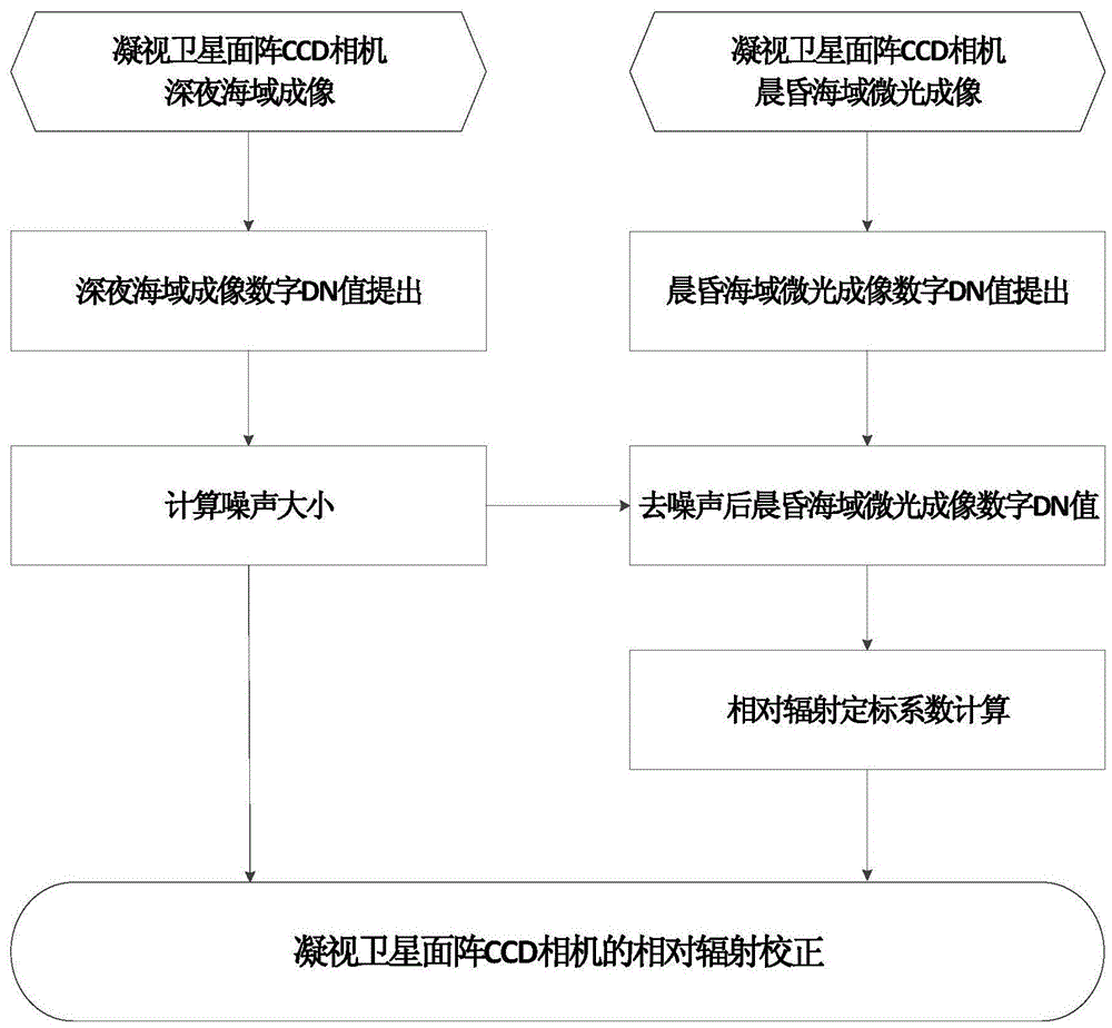
A relative radiation correction method of a staring satellite area array CCD camera is provided. The methods is characterized by, to begin with, establishing a radiation response model of detection elements of the area array CCD camera; then, utilizing the staring satellite area array CCD camera to carry out real-time and fixed-point observation on large-area deep sea far away from the land at the late night without moonlight, determining the amplitude of the noise through the remote sensing images obtained for many times, and carrying out denoising to obtain remote sensing image data without noise; then, in the morning and at dusk, utilizing the staring satellite area array CCD camera to carry out continuous imaging on the large-area deep sea far away from the land under the weak and uniformly-scattered skylight, and calculating relative radiation calibration coefficients through the remote sensing images which are obtained for many times and are denoised; and at last, obtaining a relative radiation correction image of the staring satellite area array CCD camera. The method helps to solve the technical problem of no relative radiation correction method is provided for the staring satellite area array CCD camera in in-orbit operation.

Description

technical field [0001] The invention relates to a relative radiation correction method of a staring satellite area array CCD camera, in particular to a relative radiation correction method of a geosynchronous orbit satellite area array camera. Background technique [0002] Staring satellite refers to the optical axis of the space-borne optical remote sensor "staring" at a certain point on the earth when observing the ground target, using the area array CCD two-dimensional array detector that fills the entire field of view on the star, without any mechanical movement scanning The mechanism, according to the one-to-one correspondence relationship between the detector unit on the focal plane and the scene resolution unit in the object space, can conduct continuous observation of phenomena occurring in the field of view in real time and at fixed points, and can also directly customize continuous observation according to user needs , its flexible and continuous observation method...

Claims


Application Information

Patent Timeline
Patent Type & Authority Patents(China)
IPC IPC(8): H04N5/357
Inventor 王爱春傅俏燕闵祥军陆书宁潘志强李晓进韩启金张学文刘李李照洲
Owner CHINA CENT FOR RESOURCES SATELLITE DATA & APPL
Learn More