
Half-through steel truss-concrete combined continuous steel bridge

A mid-supporting steel and concrete technology, applied in the field of bridge engineering, can solve the problems of increasing structural complexity, construction difficulty, and large building height, and achieve long-term reliable structural performance, reducing self-weight, pier and foundation structure size and The effect of the reduction of foundation bearing capacity requirements

Active Publication Date: 2014-09-10
CHONGQING JIAOTONG UNIVERSITY
View PDF7 Cites 9 Cited by
  • Summary
  • Abstract
  • Description
  • Claims
  • Application Information

AI Technical Summary

Problems solved by technology

However, the concrete bridge slab in the mid-span section still has the problem of tension cracking, and post-tensioned prestressed beams must be installed in the mid-span bridge slab to overcome the problem of tension cracking, which increases the complexity of the structure and the difficulty of construction; In addition, the height of the building above the bridge deck is large, which also limits its use range to a certain extent.

Method used


Image

  • Half-through steel truss-concrete combined continuous steel bridge
  • Half-through steel truss-concrete combined continuous steel bridge
  • Half-through steel truss-concrete combined continuous steel bridge

Examples


Embodiment Construction

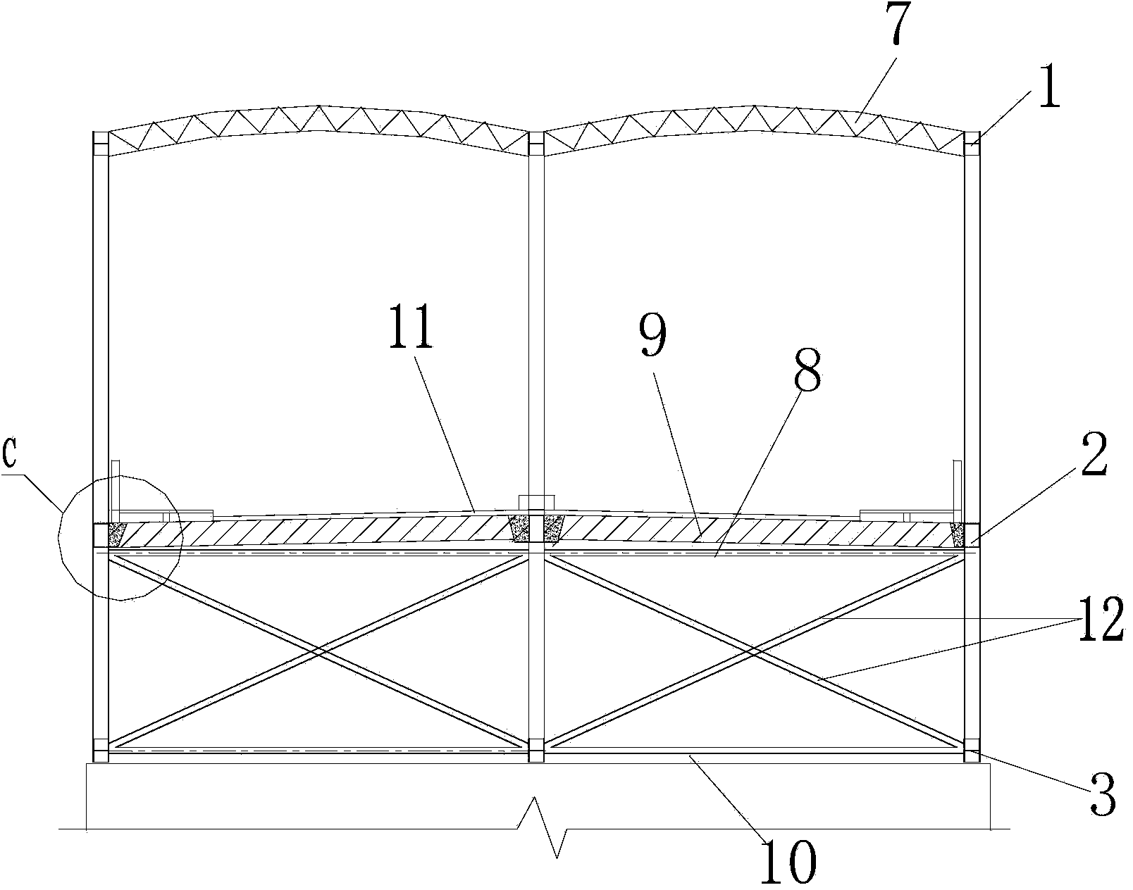
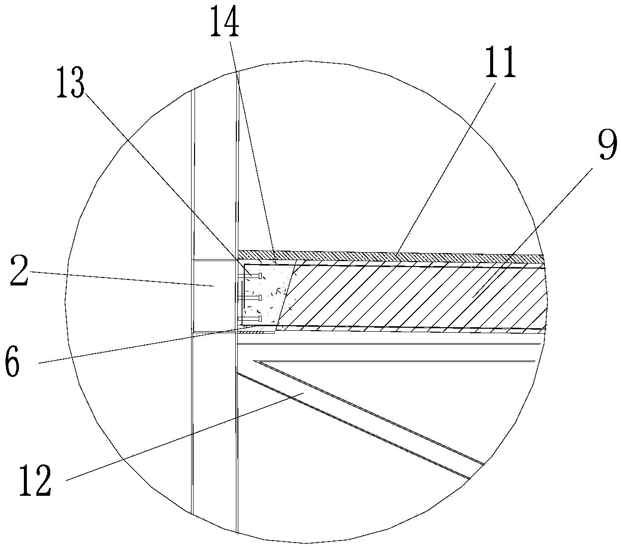
[0024] figure 1 It is a schematic diagram of the bridge structure of the present invention, figure 2 for figure 1 Sectional view along A-A direction, image 3 for figure 2 Enlarged view at C, Figure 4 for figure 1 The sectional view along B-B direction, as shown in the figure, the mid-supporting steel truss-concrete composite continuous steel bridge of this embodiment includes a main truss girder, and the main truss girder is composed of at least two steel truss girders arranged in parallel longitudinally, Steel truss beams are equipped with upper chord 1, middle chord 2 and lower chord 3;

[0025] The upper chord 1 and the middle chord 2 and between the middle chord 2 and the lower chord 3 are respectively connected through their respective webs, and the concrete bridge slab 9 is fixed between the middle chords 2 of adjacent steel truss girders to form a steel truss bridge. Box-concrete composite structure, the concrete bridge slab 9 is a cast-in-place formed concret...


PUM


Abstract

The invention discloses a half-through steel truss-concrete combined continuous steel bridge. The steel bridge comprises a main truss beam which consists of steel truss beams, wherein an upper chord, a middle chord and a lower chord are respectively arranged on each steel truss beam; a steel box-concrete combined structure formed by concrete bridge road plates is formed between the middle chords. The concrete bridge road plate is arranged at the position of the middle chord, the upper chord of the main beam in the hogging moment section of the top of a continuous steel bridge pier is pulled, the lower chord is compressed, and the concrete bridge road plate is basically positioned in the compressed section; the middle chord of the main beam in the sagging moment section of the continuous steel bridge and the combined structure with the concrete bridge road plate are the specific compressed section, the lower chord is the specific pulled section, and the problem of the cracking caused by the pulling of the concrete bridge road plate; the upper structure of the bridge is constructed in an assembly manner, the construction period is shortened, each construction link and the quality are easy to control, the stressing of the bridge is clear, and the construction is safe and fast.

Description

technical field [0001] The invention belongs to the field of bridge engineering, and in particular relates to a continuous steel structure bridge with a steel truss-concrete combination. Background technique [0002] The continuous rigid frame bridge is developed on the basis of T-shaped rigid frame and continuous girder bridge construction technologies. Both belong to the beam bridge system. Its structure is simple and it has good adaptability to V-shaped valleys. Bending member, continuous main girder body and consolidated girder pier, not only maintains the advantages of no expansion joints in the entire length of the continuous girder and smooth driving, but also maintains the advantages of T-shaped rigid frame bridge without support and no need for conversion system, which is convenient for cantilever construction. It has relatively large bending and torsional rigidity, and can meet the force requirements of super-long-span bridges. The overall performance of the struc...

Claims


Application Information

Patent Timeline
Patent Type & Authority Applications(China)
IPC IPC(8): E01D6/02E01D101/28E01D101/30
Inventor 周志祥范亮高燕梅李成君
Owner CHONGQING JIAOTONG UNIVERSITY
Learn More