Electronic part and electronic control unit
一种电子部件、电极的技术,应用在电子控制单元领域,能够解决不可能确保切断图面熔丝准确性、响应特征改变等问题,达到设计宽松、尺寸减小、降低制造成本的效果
- Summary
- Abstract
- Description
- Claims
- Application Information
AI Technical Summary
Problems solved by technology
Method used
Image

Examples
no. 1 example )
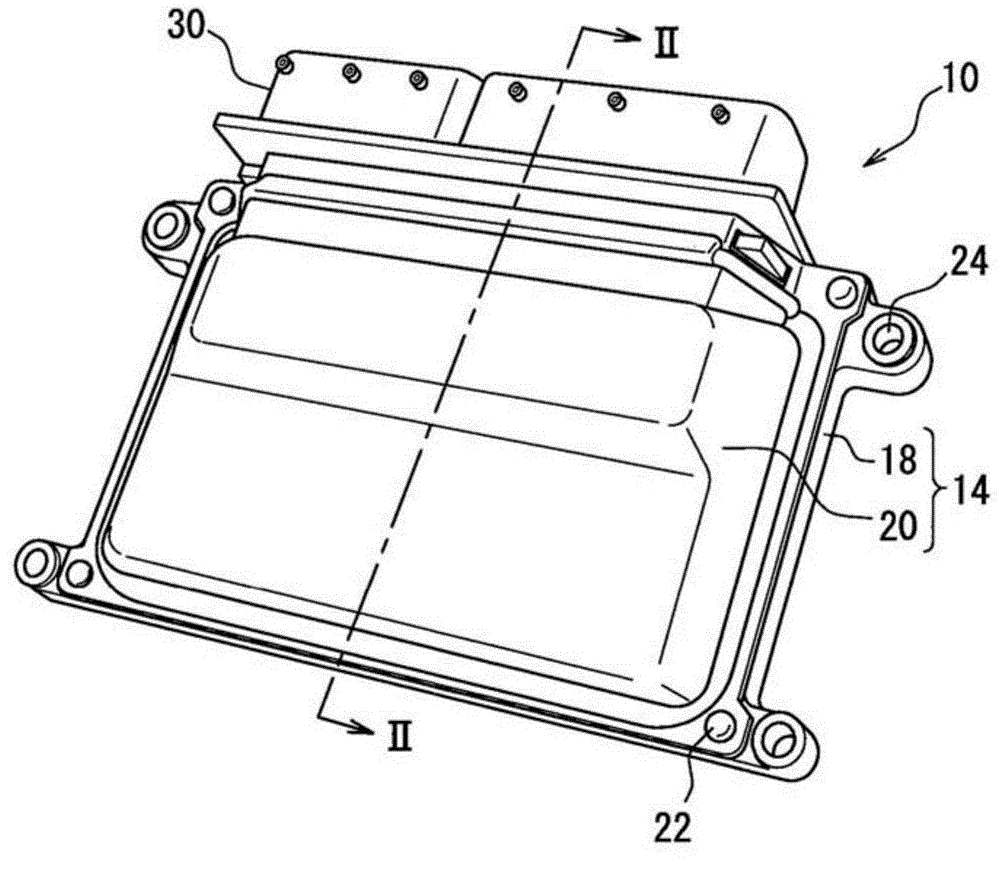
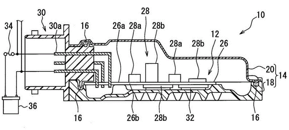
[0046] figure 1 with 2 The electronic control unit 10 is shown having a circuit board 12 as its main component. The electronic control unit 10 also has a housing 14 for receiving the circuit board 12 and a sealing element 16 . In the present embodiment, the electronic control unit 10 is formed as a watertight electronic control unit (ECU) for controlling the operation of a vehicle engine.
[0047] The outline structure of the electronic control unit 10 will be described below.
[0048]The housing 14 is made of metal (such as aluminum, iron, etc.) or a resin material for housing the circuit board 12 therein to protect it from water, dust, and the like. The number of parts used to form the housing is not limited to a specific number, and thus housing 14 may be composed of one or more components.
[0049] Such as figure 2 As shown, according to the present embodiment, the housing 14 is composed of two parts, namely, a shallow box-shaped lower housing 18 with an upper end op...
no. 2 example )
[0099] The second embodiment of the present disclosure will refer to Figure 10 illustrate. Descriptions of those parts similar or identical to those of the first embodiment (including the electronic part 28a, the electronic control unit 10, etc.) will be omitted.
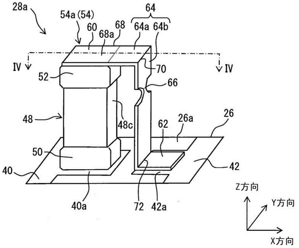
[0100] Such as Figure 10As shown, the second embodiment has a first technical feature different from that of the first embodiment. According to the first technical feature, the arm portion 78 is disposed in the fuse terminal 54a. In addition, the second embodiment has a second technical feature different from that of the first embodiment. According to the second technical feature, the cutout portion 66 is formed in the connecting portion 64 between the first connecting portion 64a and the arm portion 78, that is, closer to the electrode connecting portion 60.
[0101] The arm portion 78 extends from the second connection portion 64 b of the connection portion 64 in the X direction, that is, in a direction perpe...
no. 3 example )
[0108] The third embodiment will refer to Figure 12 illustrate. Descriptions of those parts (including the electronic part 28 a , the electronic control unit 10 , etc.) that are similar or identical to those of the first embodiment and / or the second embodiment will be omitted.
[0109] Such as Figure 12 As shown, the wiring element 80 is provided in the position of the second wiring pattern 42 of the second embodiment, wherein the wiring element 80 is made as a separate part with respect to the printed board 26 . Other parts and structures of the third embodiment are the same as those of the second embodiment (such as Figure 11 The same as those of the fourth variant shown in ).
[0110] The wiring element 80 is, for example, a bus line made of metal through which a large current flows. The pad connection portion 62 of the fuse terminal 54 a is connected (soldered) to the wiring member 80 . wiring element 80 ( Figure 12 ) and the second wiring diagram 42 (eg, Figur...
PUM
 Abstract
Description
Claims
Application Information
 - Generate Ideas
- Intellectual Property
- Life Sciences
- Materials
- Tech Scout
- Unparalleled Data Quality
- Higher Quality Content
- 60% Fewer Hallucinations
Browse by: Latest US Patents, China's latest patents, Technical Efficacy Thesaurus, Application Domain, Technology Topic, Popular Technical Reports.
© 2025 PatSnap. All rights reserved.Legal|Privacy policy|Modern Slavery Act Transparency Statement|Sitemap|About US| Contact US: help@patsnap.com