Eureka AIR delivers breakthrough ideas for toughest innovation challenges, trusted by R&D personnel around the world.

Bootstrapping diode artificial circuit in half-bridge driving circuit

A technology for simulating circuits and driving circuits, which is applied to logic circuits using semiconductor devices and logic circuits using specific components, etc. It can solve problems such as inappropriate bootstrap diode simulation circuits, insufficient driving voltage Vgate, and insufficient charging speed, etc. , achieve the effects of shortening the power-on start-up time, improving utilization efficiency and charging efficiency, and reducing on-resistance

Active Publication Date: 2014-09-03
SOUTHEAST UNIV
View PDF5 Cites 24 Cited by
  • Summary
  • Abstract
  • Description
  • Claims
  • Application Information

AI Technical Summary

Problems solved by technology

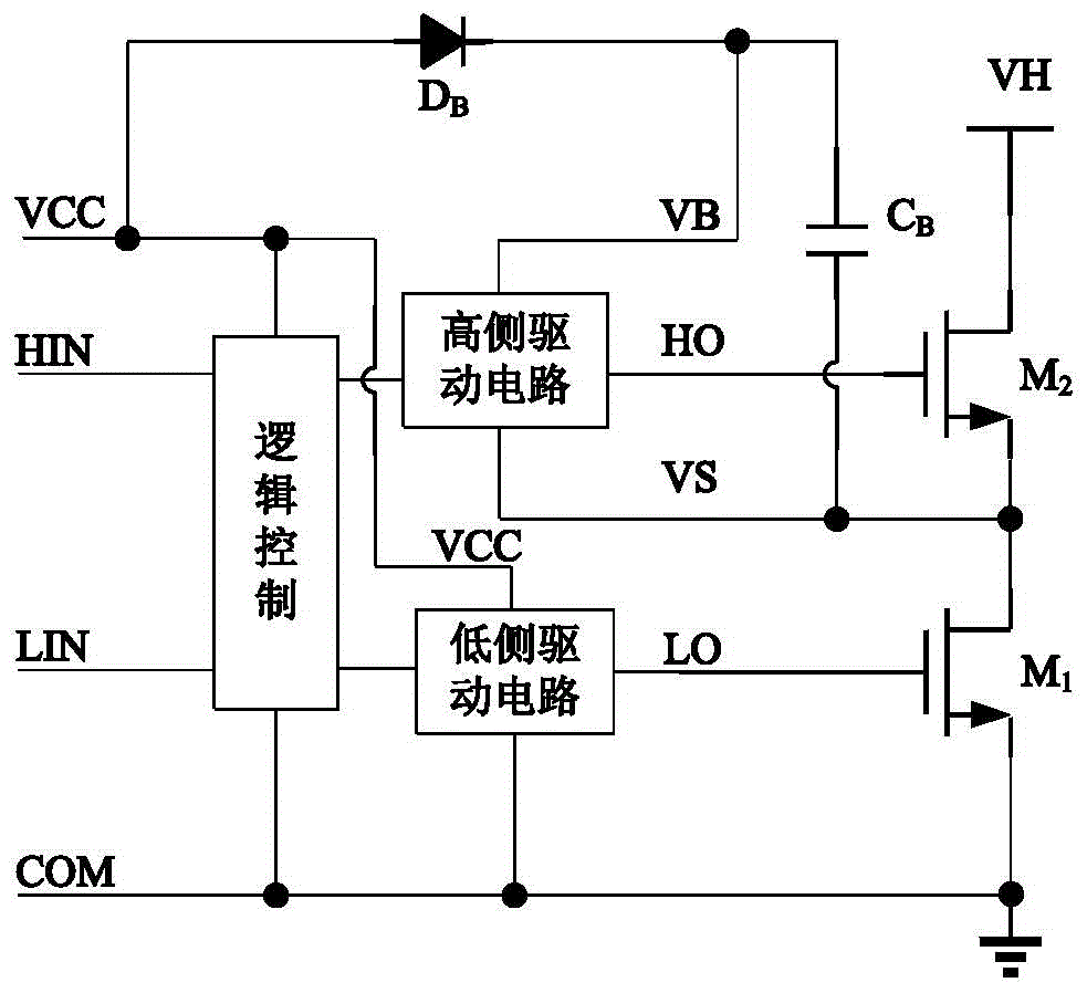
However, the drive voltage Vgate output by its gate drive circuit to the gate of the N-channel LDMOS transistor LD1 is not high enough, which makes the on-resistance of the N-channel LDMOS transistor LD1 still too high, and the charging speed is still not fast enough
This makes this conventional bootstrap diode emulation circuit unsuitable for certain applications, such as high frequency half bridge drive circuit applications

Method used


Image

  • Bootstrapping diode artificial circuit in half-bridge driving circuit
  • Bootstrapping diode artificial circuit in half-bridge driving circuit
  • Bootstrapping diode artificial circuit in half-bridge driving circuit

Examples


Embodiment Construction

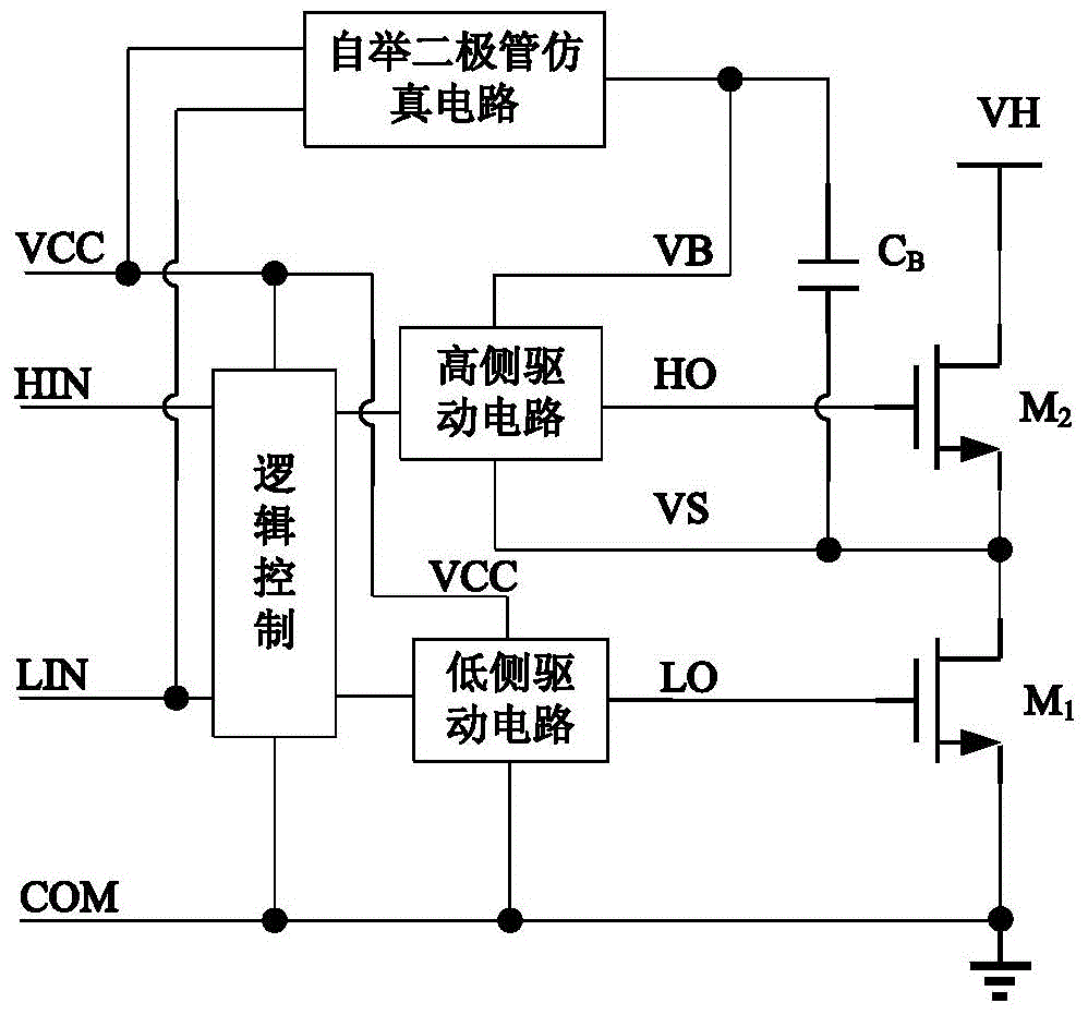
[0020] The half-bridge drive circuit of the present invention and figure 2 U.S. Patent No. 7215189 B2 is the same, when the output LO of the low-side drive circuit is high level so that the power transistor M 1 When turned on, the bootstrap diode emulation circuit allows current to flow from the low-side supply voltage VCC through the bootstrap diode emulation circuit and the power transistor M 2 to the bootstrap capacitor CB charges, thus the bootstrap capacitor C B Charge to close to the low-side supply voltage VCC. When the power tube M 2 is turned on while the power transistor M 1 During shutdown, the bootstrap diode emulation circuit prevents current flow from the low-side supply voltage VCC to capacitor C B , thus stored in the bootstrap capacitor C B The charge in provides voltage for the high-side drive circuit.

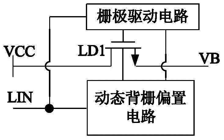
[0021] Bootstrap diode simulation circuit of the present invention and image 3 Similarly, the dynamic backgate biasing circuit in the bootstrap diod...


PUM


Abstract

The invention provides a bootstrapping diode artificial circuit in a half-bridge driving circuit. An electrical level displacement and a simple charge pump are added into a grid driving circuit structure in an existing bootstrapping diode artificial circuit; when a grid driving input signal is a low electrical level, grid voltage output to an N-channel LDMOS (Lateral Diffusion Metal Oxide Semiconductor) transistor LD1 by a grid driving circuit is a low electrical level; the N-channel LDMOS transistor LD1 is turned off. When the grid driving input signal is a high electrical level, the grid voltage output to the N-channel LDMOS transistor LD1 by the grid driving circuit is a high electrical level so that the grid voltage of the N-channel LDMOS transistor LD1 is improved, the conduction resistance of the LD1 is reduced and the charging current to a bootstrapping capacitor is improved.

Description

technical field [0001] The invention relates to a half-bridge driving circuit, in particular to a bootstrap diode emulation circuit in the half-bridge driving circuit. Background technique [0002] The half-bridge drive circuit is widely used in the fields of motor drive, electronic ballast, switching power supply, etc. It is used to drive two power MOS tubes or IGBTs connected in the form of totem poles to make them conduct alternately. In addition to the high-voltage level shift circuit used as the interface between the high-side and low-side circuits inside the half-bridge drive circuit (it is located on the edge of the isolation structure and needs to work at a voltage of several hundred volts), other circuit modules are located in the high-voltage area ( High-side power supply) and low-voltage area (low-side power supply), both work at a voltage of 10 to 20 volts. In order to improve the utilization efficiency of the power supply, only a single power supply is used. The...

Claims


Application Information

Patent Timeline
Patent Type & Authority Applications(China)
IPC IPC(8): H03K19/08
Inventor 孙伟锋黄泽祥张允武祝靖陆生礼时龙兴
Owner SOUTHEAST UNIV
Why Eureka
Eureka Blog
Learn More