
Anti-bypass type direct safety injection deflector and direct safety injection device

A direct, flow-type technology, applied in cooling devices, reactors, and reducing greenhouse gases, etc., can solve problems such as large thermal stress at the welding point, reduce the service life of safety injection nozzles, and sharp turns of safety injection water, so as to improve diversion Good diversion and guiding effect, solve the effect of poor anti-bypass flow

Active Publication Date: 2017-01-04
CHINA NUCLEAR POWER TECH RES INST CO LTD +1
View PDF7 Cites 0 Cited by
  • Summary
  • Abstract
  • Description
  • Claims
  • Application Information

AI Technical Summary

Problems solved by technology

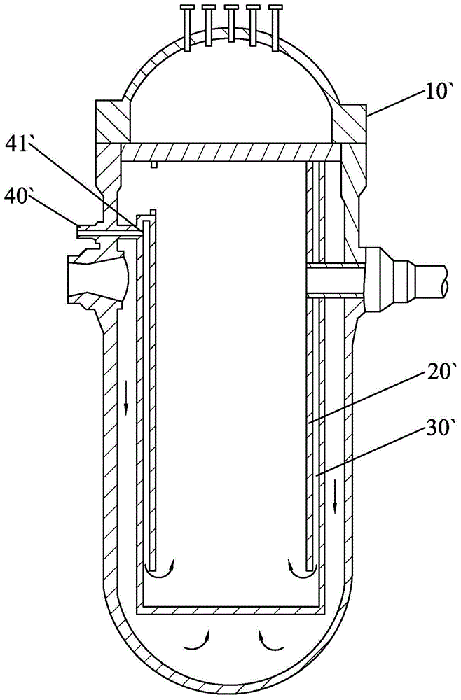
like figure 1 As shown, the U.S. Patent Publication No. US5377242 discloses a safety injection device, which is to arrange a rectangular chamber 30 ′ between the pressure vessel 10 ′ and the hanging basket 20 ′, and directly install the injection nozzle 40 ′. The outlet 41' is opposite to the inlet of the rectangular chamber 30', and there is no transitional flow guiding part between them, so that the safe injection water flows directly along the rectangular chamber 30' to the bottom of the pressure vessel 10', Accelerate the flow of safety injection water to the core; the safety injection device is not equipped with a flow guide device in the middle, so that the pipeline and pressure vessel 10` are subjected to a large thermal shock force during the safety injection process, and the safety injection water flows along the rectangular chamber 30 `The downward flow is uneven, resulting in shocks and poor anti-bypass performance
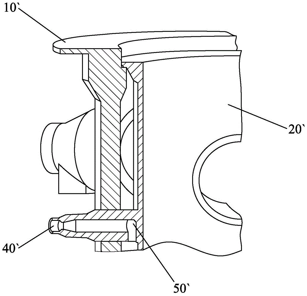
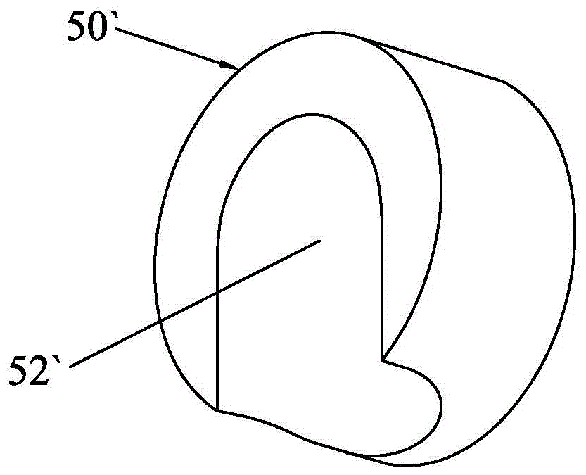
[0009] like figure 2 , Figure 3a and Figure 3b As shown, the U.S. Patent Publication No. US7889830B2 discloses a safety injection device, the safety injection device has a flow guiding device 50 ′, and the flow guiding device 50 ′ is a shallow groove structure with a groove 51 ′. The position of the injection nozzle 40' is processed with a radian structure 52' that guides the safety injection water to change its direction. , the flow direction of the safety injection water changes, that is, it flows downward; the diversion device is installed on the hanging basket 20`, limited by the thickness of the hanging basket 20`, its arc radius is very small, so that the turning of the safety injection water is too sharp , the safety injection water cannot be organized to flow downward in a good and orderly manner, so that the safety injection water will vibrate violently when the safety injection water flows downward, and the anti-side flow is poor; at the same time, because its diversion device is welded on the hanging basket 20`, it is difficult for the subsequent hanging basket 20`. The installation process of the basket 20` and the docking work with the direct injection nozzle 10` brought certain technical difficulties
[0010] like Figure 4 As shown, the U.S. Patent Publication No. US7983377B2 discloses a safety injection device. The diversion device of the safety injection device disclosed in this patent is to install a diversion channel 21` on the hanging basket 20`, and directly install the injection nozzle 40` Facing the opening of the diversion channel 21`, on the one hand, when the safety injection process occurs, the initial flow rate and impact force of the safety injection water are relatively large, and the turning radius of the safety injection water in the diversion channel 21` is relatively small , so that the safety injection water cannot completely flow downward in an orderly manner along the diversion channel 21`, so that the safety injection water will generate violent shocks when flowing downward, and the anti-side flow is poor; on the other hand, due to the safety injection nozzle 40` and There is no transition structure between the pressure vessels 10`, and the thermal stress on the weld between the direct safety injection nozzle 40` and the pressure vessel 10` is relatively large during the safety injection process, which greatly reduces the service life of the safety injection nozzle

Method used


Image

  • Anti-bypass type direct safety injection deflector and direct safety injection device
  • Anti-bypass type direct safety injection deflector and direct safety injection device
  • Anti-bypass type direct safety injection deflector and direct safety injection device

Examples


Embodiment Construction

[0035] Embodiments of the present invention will now be described with reference to the drawings, in which like reference numerals represent like elements.

[0036] Such as Figure 5-Figure 9b As shown, the direct injection device 100 of the present invention includes a direct injection nozzle 40 and an anti-bypass type direct injection guide 50, and the anti-bypass type direct injection guide 50 and the direct injection tube The outlet 41 of the nozzle 40 is docked to guide the safe injection water, wherein the anti-bypass type direct injection guide 50 includes a hollow and downwardly bent guide tube body 51, and the guide tube The body has an inlet 52 and a downward outlet 53, the inlet 52 is connected to the outlet 41 of the direct injection nozzle 40, and the outlet 53 is in a flat structure, and the inlet The calibers from the outlet port 52 to the outlet port 53 gradually increase. Specifically, the diversion pipe body 51 of the present invention can use the direct sa...


PUM


Abstract

The invention discloses a side-stream-prevention direct safely injecting stream guide element which is suitable for butt joint with a direct safely injecting pipe nozzle outlet and then is used for guiding safely injected water. The side-stream-prevention direct safely injecting stream guide element is characterized by comprising a stream guide pipe body which is hollow and bends downward and is provided with a stream inlet and a stream outlet downward, wherein the stream inlet is in butt joint and communicated with the direct safely injecting pipe nozzle outlet; the stream outlet is of a flat structure, and the caliber from the stream inlet to the stream outlet increases gradually. The side-stream-prevention direct safely injecting stream guide element has a favorable stream guide property, guiding property and side stream prevention property by virtue of the stream guide pipe body bending downwards and the stream outlet with the flat structure. Additionally, the invention also discloses a direct safely injecting device with the side-stream-prevention direct safely injecting stream guide element.

Description

technical field [0001] The invention relates to nuclear reactor safety equipment, in particular to an anti-bypass direct safety injection guide piece and a direct safety injection device for a nuclear reactor pressure vessel. Background technique [0002] With the maturity of nuclear energy utilization technology, the safety of nuclear power plants has been continuously improved, and the construction of nuclear power plants has gradually become an important energy guarantee for national development. [0003] In current nuclear power plants, the structure of the nuclear reactor is as follows: a reactor chamber is formed in the containment vessel, and a pressure vessel is arranged in the reactor chamber. The pressure vessel is connected with a cold pipe section and a hot pipe section, and coolant is injected through the cold pipe section to cool the pressure vessel, and then discharged through the hot pipe section. [0004] When a nuclear reactor has a broken cold pipe sectio...

Claims


Application Information

Patent Timeline
Patent Type & Authority Patents(China)
IPC IPC(8): G21C15/18
CPCY02E30/30
Inventor 卢冬华苏前华王阔梁振辉邢军
Owner CHINA NUCLEAR POWER TECH RES INST CO LTD
Learn More