Braking method and system for an electric vehicle

An electric vehicle, friction braking technology, applied in the direction of electric braking system, braking control system, braking system interaction, etc., can solve the problems of electric vehicle efficiency reduction, reduction of recovery and corresponding power generation deceleration torque, etc., to achieve The effect of high recovery and high efficiency

Pending Publication Date: 2020-03-13
AUDI AG
View PDF9 Cites 0 Cited by
  • Summary
  • Abstract
  • Description
  • Claims
  • Application Information

AI Technical Summary

Problems solved by technology

It is precisely in the limit range of the driving dynamics of electric vehicles that the recuperation and the corresponding decel...

Method used


Image

  • Braking method and system for an electric vehicle
  • Braking method and system for an electric vehicle
  • Braking method and system for an electric vehicle

Examples


Embodiment Construction

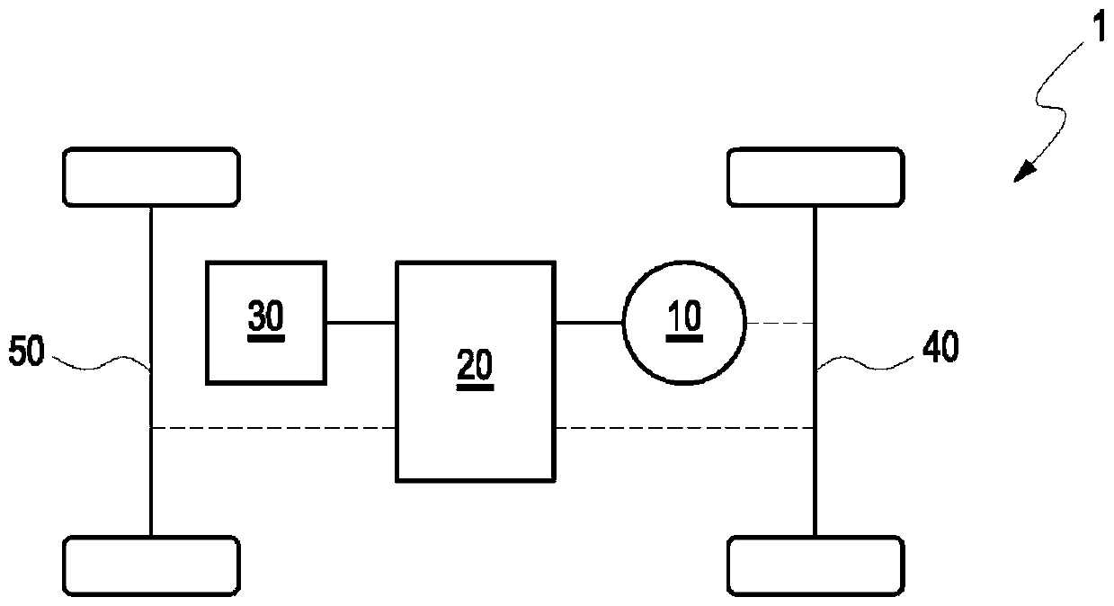
[0042] figure 1 A block diagram of an electric vehicle 1 according to the present invention is shown. The electric vehicle 1 includes a motor 10 and a friction braking system 20, a first axle 40 configured as a rear axle that can be decelerated by the motor 10 and the friction braking system 20, and a front axle that can only be decelerated by the friction braking system 20 The second axle 50 of the.

[0043] Furthermore, the electric vehicle 1 comprises a controller 30 and an actuating element in the form of a brake pedal, not shown, connected to the friction braking system 20 and the controller 30, through which the driver of the electric vehicle can determine the The total deceleration torque of electric vehicle 1.

[0044] The controller 30 is configured to control the motor 10 and the friction braking system 20 to provide the axle deceleration torque for the first axle 40 and the axle deceleration torque for the second axle 50, wherein, according to the electric vehicle...


PUM


Abstract

A method for braking an electric vehicle in which a first axle of an electric vehicle is decelerated by an electric motor of the electric vehicle and/or by a friction brake system of the electric vehicle.

Description

technical field [0001] The invention relates to a braking method for an electric vehicle, wherein a motor of the electric vehicle and / or a friction braking system of the electric vehicle provide deceleration torque for the first axle of the electric vehicle. Background technique [0002] Like vehicles driven by an internal combustion engine, electric vehicles have a mostly hydraulic friction braking system, which is designed to provide a deceleration torque to the wheels of the electric vehicle by acting on the wheels via friction. The deceleration torque is opposite to the rotation of the wheels to brake or stop the electric vehicle, that is, to reduce the driving speed of the electric vehicle. Modern friction braking systems distribute the supplied deceleration torque dynamically and variably to the wheels and / or axles of electric vehicles. [0003] The patent document DE 10 2013 203 824 A1 discloses a braking method for a vehicle having a hydraulic friction braking syste...

Claims


Application Information

Patent Timeline
IPC IPC(8): B60L7/24B60T13/58
CPCB60L7/24B60T13/58B60T13/585B60T8/1755B60T2270/604B60T2270/613B60L3/108B60L7/26B60L2240/22B60L2240/423B60L15/2009Y02T10/72Y02T10/64Y02T10/70B60T8/17552B60T8/321B60L7/18B60T2240/00B60T2250/03B60T2250/00B60T2260/00B60T2270/304B60T2230/00
Inventor M·戈伊斯
Owner AUDI AG
Why Eureka
Try Eureka