
High-temperature pressurization airflow solid particle erosive wear testing device

A solid particle and testing device technology, which is applied in the direction of testing wear resistance, etc., can solve the problems of difficult particle velocity measurement, inaccuracy, and unsuitable precise control of velocity and angle

Inactive Publication Date: 2014-08-27
BEIJING INSTITUTE OF PETROCHEMICAL TECHNOLOGY
View PDF12 Cites 23 Cited by
  • Summary
  • Abstract
  • Description
  • Claims
  • Application Information

AI Technical Summary

Problems solved by technology

[0003] At present, the test equipment for solid particle erosion wear research at home and abroad is not perfect, and there is no ideal solid particle erosion wear test device.
Some experimental equipment commonly used today cannot accurately control the main factors of the wear process (particle impact velocity, impact angle and impact density, etc.) and simulate actual working conditions (such as: high temperature, high pressure, high speed and certain corrosive gas environment working conditions), which limits the scope of some experimental conditions to a certain extent
For example, the vacuum drop test device is only suitable for low-speed tests (the speed is generally less than 5m / s); the centrifugal abrasive acceleration test device has the disadvantages that the speed and angle are not suitable for precise control; The impact speed is caused by mechanical rotation, so it is very important to control the constant speed of the motor; the feeding of the jet erosion wear tester is difficult and the particle velocity measurement is not accurate enough
The mechanism of erosion and wear is complex, involving the interaction between solid particles and materials, but the erosion velocity is unknown and the change is complex. The distance between the nozzle outlet and the sample is relatively short, and for safety reasons, it is difficult to observe the movement of erosion particles. At present, the speed range of particles in the erosion process and the resulting material wear mechanism have not been well explained at home and abroad.

Method used


Image

  • High-temperature pressurization airflow solid particle erosive wear testing device
  • High-temperature pressurization airflow solid particle erosive wear testing device

Examples


specific Embodiment

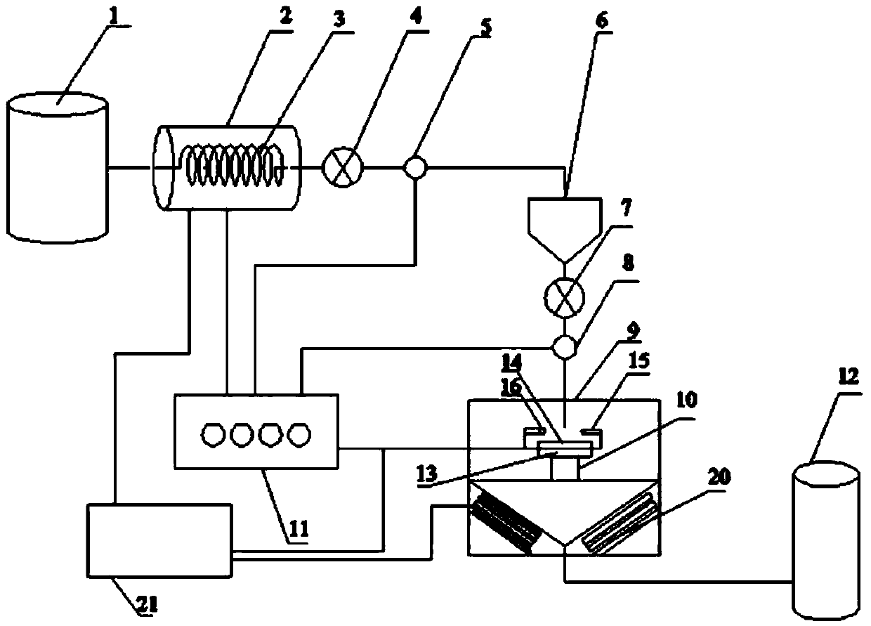
[0027] Such as figure 1 and figure 2 shown in figure 1 Among them, this embodiment includes an air compressor 1, a high-temperature air heater 2, a box body 9, an electronic high-temperature control valve 4, a gas flow meter 5, a solid particle feeder 6, a solid flow regulating valve 7, a solid flow meter 8, and a test Sample rack 10 and display 11. The gas generated by the air compressor 1 is heated by the high-temperature air heater 2. The gas outlet of the high-temperature air heater 2 is equipped with an electronic high-temperature control valve 4 and a gas flow meter 5 to adjust and display the gas supply pressure. The gas outlet of the high-temperature air heater 2 It is connected with the upper cavity of the closed solid particle feeder 6 . A solid flow regulating valve 7 and a solid flow meter 8 are provided at the outlet of the solid particle feeder 6 to control the amount of erosion. The solid particles complete the erosion process in the box 9. The circulation...


PUM


Abstract

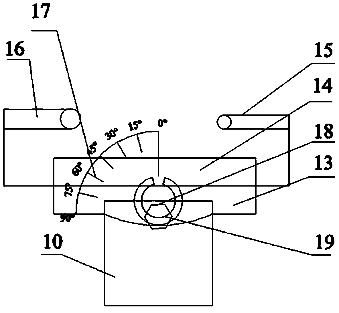
The invention discloses a high-temperature pressurization airflow solid particle erosive wear testing device. The high-temperature pressurization airflow solid particle erosive wear testing device comprises an air compressor, a high-temperature air heater, an electronic high-temperature control valve and an air flowmeter, wherein the air compressor, the high-temperature air heater, the electronic high-temperature control valve and the air flowmeter are connected in sequence through pipes. An air outlet pipe of the air flowmeter is connected with an upper cavity of a closed type solid particle feeder, and a discharging port pipe of the solid particle feeder stretches into a box through a solid flow regulating valve and a solid flowmeter. A specimen holder is arranged inside the box, a specimen heater is arranged on the specimen holder, an outlet of the solid flowmeter right faces the position above the specimen heater, and an infrared speed meter and a high-speed camera are arranged above the specimen heater. The high-temperature pressurization airflow solid particle erosive wear testing device can be widely applied to the field of erosive wear and suitable for high-temperature erosive wear testing of various materials.

Description

technical field [0001] The invention relates to an erosion and wear test equipment, in particular to a high-temperature pressurized gas flow solid particle erosion and wear test device. Background technique [0002] Erosion wear is one of the common wear forms in modern industrial production, and it is an important cause of material damage or failure. During the erosion process, the airflow entrains solid particles to erode the surface of the material at a certain speed and angle, resulting in material loss. In coal, electric power, chemical industry, metallurgy, mining, petroleum, aerospace, construction and other industries, there are a large number of solid particle erosion and wear phenomena and cause great harm. Among them, the combustion exhaust gas of pulverized coal boilers in thermal power plants is involved in the high-temperature erosion and wear process of heat exchanger pipes, and the broken catalyst particles entrained by high-temperature flue gas in petrochem...

Claims


Application Information

Patent Timeline
IPC IPC(8): G01N3/56
Inventor 张洪伟董晓慧蔡晓君陈曙光
Owner BEIJING INSTITUTE OF PETROCHEMICAL TECHNOLOGY
Learn More