
Sensorless vector control device and method for non-salient pole type permanent magnet synchronous motor

A technology of permanent magnet synchronous motor and vector control, which is applied in vector control system, motor generator control, control of electromechanical transmission, etc., and can solve problems such as performance change, limited low-speed expansion field, sensorless control failure, etc.

Active Publication Date: 2014-08-20
ZHEJIANG SCI-TECH UNIV
View PDF9 Cites 37 Cited by
  • Summary
  • Abstract
  • Description
  • Claims
  • Application Information

AI Technical Summary

Problems solved by technology

[0003] Patent Documents 5 and 6 design a traditional sliding mode observer to estimate the rotor position information. After a large number of experiments by the applicant, this method has found that its low-speed expansion area is limited, and there is a phenomenon that the rotor angle error changes from time to time during the motor speed change process. Even if It is a fixed speed operation, and the performance will change after a long time, especially when the load is applied, the sensorless control basically fails, which limits the further application of the sliding mode observer in the sensorless closed-loop control of the PMSM to a certain extent

Method used


Image

  • Sensorless vector control device and method for non-salient pole type permanent magnet synchronous motor
  • Sensorless vector control device and method for non-salient pole type permanent magnet synchronous motor
  • Sensorless vector control device and method for non-salient pole type permanent magnet synchronous motor

Examples


Embodiment 1

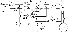
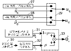
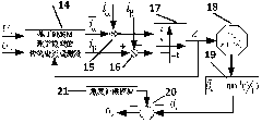
[0026] Embodiment 1, figure 1 , figure 2 with Figure 4 A sensorless vector control device and method for a hidden pole permanent magnet synchronous motor is presented.

[0027] Such as figure 1 As shown, the sensorless vector control device of the hidden pole permanent magnet synchronous motor includes a first subtractor 1, a speed loop integral separation PI module 2, a second subtractor 3, a third subtractor 4, and a current loop integral separation PI module 5 , phase-locked loop speed estimation module 6, sensorless closed-loop control module 7 based on position self-adjusting voltage vector switching, PARK transformation module 8, IPARK transformation module 9, space vector modulation module 10, CLARK transformation module 11 and rectification / three-phase inverter Transformer 12; The signal connection relation of the present invention is as follows:

[0028] The permanent magnet synchronous motor 13 obtains the two-phase current i through the built-in sensor a i b ,...


PUM


Abstract

The invention discloses a sensorless vector control device for a non-salient pole type permanent magnet synchronous motor. The sensorless vector control device comprises a sensorless closed-loop control module based on position self-adjusting voltage vector switching and the like. The permanent magnet synchronous motor is connected with a CLARK conversion nodule. The CLARK conversion nodule is respectively connected with the sensorless closed-loop control module based on position self-adjusting voltage vector switching and an IPARK conversion module. The IPARK conversion module is respectively connected with a first subtracter, a second subtracter and a third subtracter. The first subtracter and the second subtracter are connected with a speed ring integral separation PI module. A current ring integral separation PI module is connected with the sensorless closed-loop control module based on position self-adjusting voltage vector switching. The sensorless closed-loop control module based on position self-adjusting voltage vector switching is respectively connected with a phase-locked loop rotating speed estimation module and a PARK conversion module, and the PARK conversion module is connected with the sensorless closed-loop control module based on position self-adjusting voltage vector switching and a space vector modulation module. The space vector modulation module is connected with a rectification / three-phase inverter, and the rectification / three-phase inverter is connected with the permanent magnet synchronous motor.

Description

technical field [0001] The invention relates to a motor motion control technology, in particular to a sensorless vector control device and method for a hidden pole permanent magnet synchronous motor. Background technique [0002] In view of the sensorless (position) sensorless control technology, the permanent magnet synchronous motor vector control speed control system has a simple structure, easy maintenance, small size, and does not have limitations and defects brought by mechanical sensors to the system (such as limited by the working environment, reduced reliability, etc. ), so it is suitable for some special occasions, such as variable frequency drives in the field of textile machinery, home-commercial air conditioners, refrigerators, washing machines, electric tourist vehicles, electric golf carts, electric patrol cars, industrial pumps, fans, mining machine lifting, High-power traction for locomotives, air conditioners for electric vehicles for military use, and so o...

Claims


Application Information

Patent Timeline
IPC IPC(8): H02P21/00H02P21/14H02P21/04
Inventor 鲁文其刘虎袁嫣红
Owner ZHEJIANG SCI-TECH UNIV
Learn More