Eureka AIR delivers breakthrough ideas for toughest innovation challenges, trusted by R&D personnel around the world.

Electric power steering system

a technology of electric power steering and steering wheel, which is applied in the direction of steering initiation, dynamo-electric converter control, dynamo-electric gear control, etc., can solve the problems of motor not being able to generate proper torque, motor not being able to generate large torque, problem cannot be avoided, etc., to prolong the braking period for restraining the rotation of the steering wheel, the effect of high speed rotation sta

Inactive Publication Date: 2013-01-10
TOYOTA JIDOSHA KK
View PDF5 Cites 36 Cited by
  • Summary
  • Abstract
  • Description
  • Claims
  • Application Information

AI Technical Summary

Benefits of technology

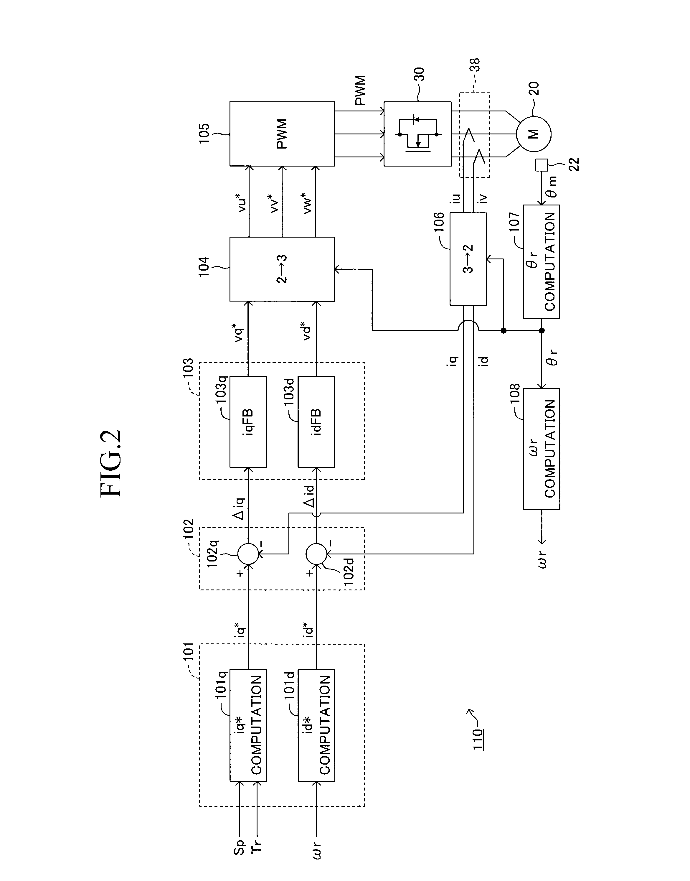
The present invention relates to a control system for a vehicle's steering wheel. The technical effect of this invention is that it reduces the discomfort feel that drivers may have when the steering wheel is rotated by reverse input. Additionally, it reduces the time delay in controlling the motor that drives the steering wheel, even when it is rotating at extreme speeds. This is achieved by using a map that defines the relation between the motor's speed and the phase angle of the output voltage vector in relation to the d-axis. This enables a faster computation of the second phase angle, which is a smaller amount of computation per control period than the first phase angle.

Problems solved by technology

However, in actuality, since the rotational speed of the steering wheel; i.e., the rotational speed of the motor, is very high, the motor cannot generate a large torque.
This problem cannot be avoided because of the characteristics of the brushless DC motor.
However, in actuality, since the speed at which the motor is rotated by the reverse input is extremely high, a proper torque cannot be generated because of the insufficient computation performance of a microcomputer used in the conventional assist control apparatus.
One cause which makes the computation performance of the microcomputer insufficient is that the assist control apparatus performs two-degree-of-freedom control; i.e., controls the d-axis current and the q-axis current.
Also, since a calculation formula for obtaining the optimum d-axis target current is complex, the d-axis target current is calculated through use of a map in which a limited number of parameters are used.
Therefore, the d-axis target current calculated through use of such a map is not optimum.

Method used


Image

  • Electric power steering system
  • Electric power steering system
  • Electric power steering system

Examples


second embodiment

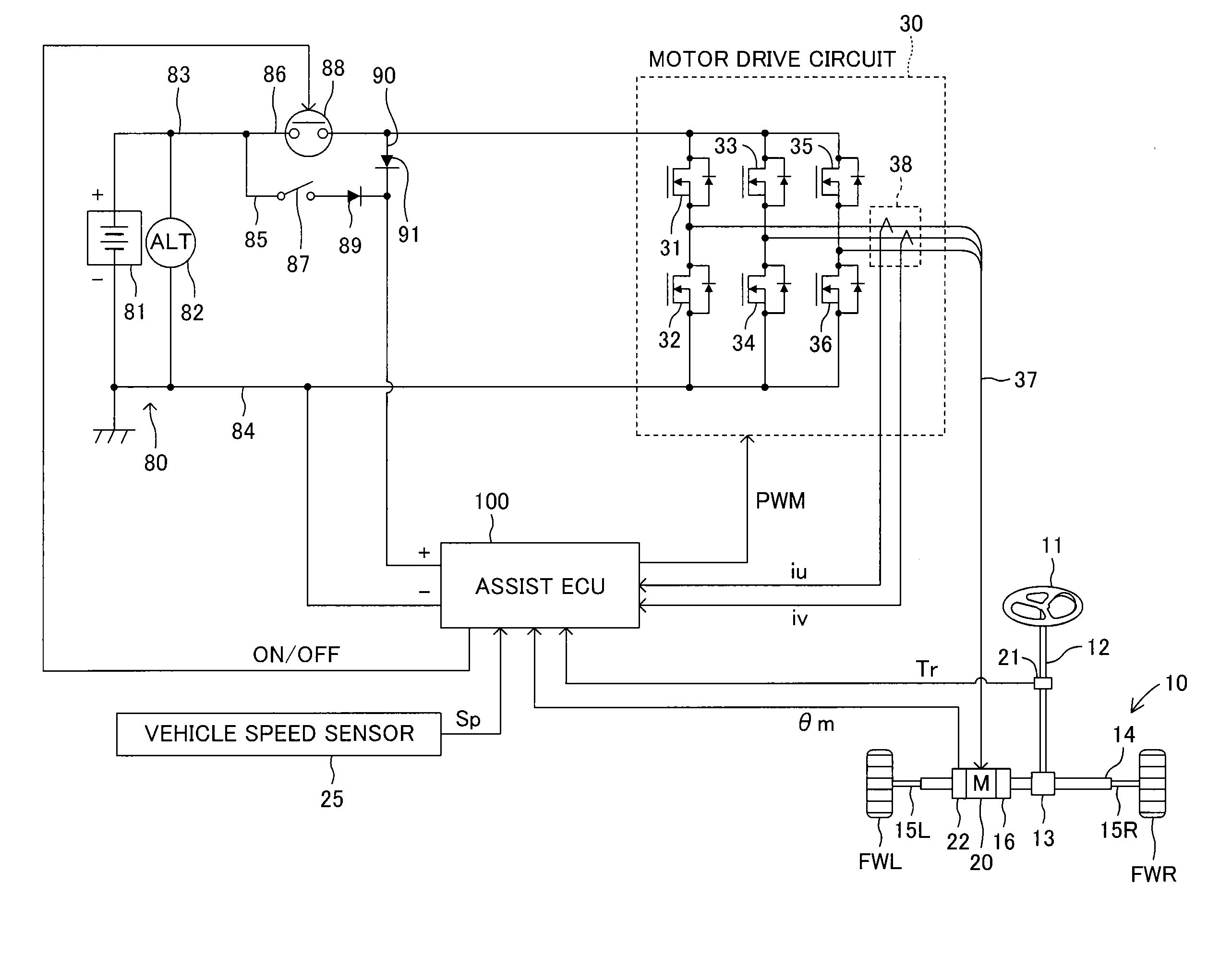
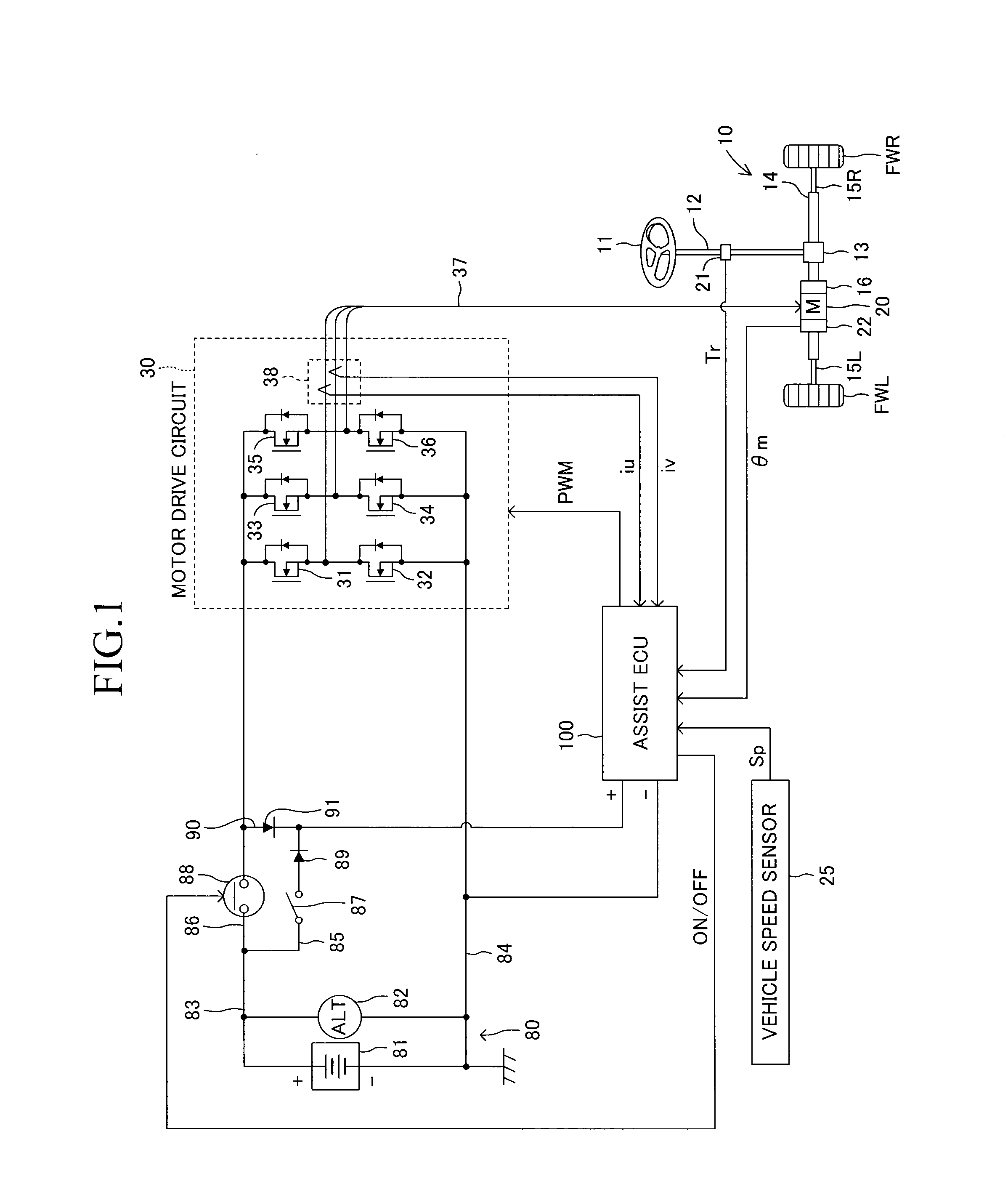
[0193]First, control mode changeover will be described. FIG. 20 shows a mode changeover control routine of the The mode changeover control routine is stored, as a control program, in the ROM of the microcomputer of the assist ECU 100, and is repeatedly executed at predetermined intervals when the ignition key is held at the ON position.

[0194]Upon starting the mode changeover control routine, in step S21, the assist ECU 100 determines whether or not the rotational speed |ωr| is greater than the second threshold ωth2. This second threshold ωth2 is a fixed value which is set such that it is greater than the first threshold ωth1.

[0195]In the case where the rotational speed |ωr| is equal to or less than the second threshold ωth2 (S21: No), the assist ECU 100 performs the processing of steps S22 and S23, which is similar to that of the steps S11 and S12 of the first embodiment. Specifically, in step S22, the assist ECU 100 computes the rotational acceleration A of the motor 20; and, in s...

first embodiment

[0207]The voltage phase instruction value θc computed by the addition section 202 is output to the PWM signal generation section 203. The PWM signal generation section 203 generates, in accordance with the voltage phase instruction value θc, PWM control signals which are set such that the output voltages of the motor drive circuit 30 become the sinusoidal wave voltages expressed by the following expression (17), and outputs the PWM control signals to the switching elements 31 to 36. In this case, the amplitude V of each sinusoidal wave voltage is also determined from the voltage limit value of the motor drive circuit 30 as in the case of the

{Vu=Vsin(θmap+θr)Vv=Vsin(θmap+θr-2π3)Vw=Vsin(θmap+θr-4π3)(17)

[0208]The switching elements 31 to 36 operate in response to the PWM control signals output from the PWM signal generation section 203. Thus, the motor drive circuit 30 outputs three-phase sinusoidal wave voltages.

[0209]In the case of the electric power steering apparatus of the second ...


PUM


Abstract

A feedforward control section computes, on the basis of a target current absolute value, a voltage limit value of a motor drive circuit, and a rotational speed ωr of a motor, a phase angle of a voltage vector which represents the output voltage of the motor drive circuit by a d-q coordinate system, the phase angle being a phase angle in relation to the d-axis of the d-q coordinate system. A feedback control section computes a phase angle based on a deviation between the target current absolute value and the actual current absolute value. A PWM control signal generation section outputs PWM control signals such that the motor drive circuit outputs a three-phase drive voltage whose electrical angle is advanced by a phase angle. Thus, in the case where a large reverse input is applied to a steering mechanism, the motor is caused to generate a large torque to thereby prevent the steering wheel from being rotated.

Description

TECHNICAL FIELD[0001]The present invention relates to an electric power steering system or apparatus which drives and controls an electric motor in accordance with a driver's steering operation, to thereby generate steering assist torque.BACKGROUND ART[0002]Conventionally, an electric power steering apparatus sets a target assist torque on the basis of a steering operation performed by a driver, and controls the supply of electricity to a motor such that the target assist torque is applied to a steering mechanism. Also, there is known an electric power steering apparatus in which a brushless DC motor is used as such a motor. In the case where a brushless DC motor is employed, in general, the supply of electricity to the motor is controlled through use of vector control represented by a two-phase rotating magnetic flux coordinate system (d-q coordinate system). Such control of the supply of electricity to the motor is carried out by an assist control apparatus including a microcomput...

Claims


Application Information

Patent Timeline
Patent Type & Authority Applications(United States)
IPC IPC(8): B62D6/00B62D5/04H02P21/00H02P27/04H02P21/22H02P25/026H02P27/08
CPCB62D5/046B62D5/0481B62D5/0472
Inventor AOKI, KENICHIRO
Owner TOYOTA JIDOSHA KK
Why Eureka
Eureka Blog
Learn More