
A coil winding device

A technology of winding device and unwinding device, which is applied to the manufacture of transmission parts, electrical components, inductors/transformers/magnets, etc. Winding accuracy, easy coil take-out, and labor-saving effects

Active Publication Date: 2016-06-08
SICHUAN PROVINCE KUWAIT ELECTRICAL
View PDF6 Cites 0 Cited by
  • Summary
  • Abstract
  • Description
  • Claims
  • Application Information

AI Technical Summary

Problems solved by technology

At present, most coil production industries usually complete the winding of the coil manually. Before winding, the rolled rubber is unrolled in the workshop, and then the rolled metal plate is unrolled and covered on the rubber, and then another roll is rolled The rubber is unfolded and covered on the metal plate, and finally only the three-layer material is rolled up to make a coil for high-voltage wires. This processing method undoubtedly increases the workload of workers and wastes the space in the workshop. Disadvantages of lower yield
[0003] At present, the existing coil winding device is composed of a drum and two sliding bearings. The two ends of the drum are respectively installed on the two sliding bearings. Before winding, the rolled metal plate and the rolled rubber are respectively installed on the uncoiler. , and then pull the head end of the rubber onto the roller, and then pull the head end of the metal plate onto the roller. At this time, it is only necessary to turn the roller to process the coil. However, due to the wear and tear of the sliding bearing for a long time, the The drum drive jumps, which eventually leads to the staggering of the rubber layer and the metal plate layer, which affects the quality of the coil, and can only be treated as waste in the end. This undoubtedly increases the production cost and seriously reduces the economic benefits of the enterprise. In addition, the coil is tightly attached to the drum. Only by opening the two sliding bearings and lifting the drum out can the coil be taken out from the drum, which undoubtedly brings difficulties to the workers' operation

Method used


Image

  • A coil winding device
  • A coil winding device
  • A coil winding device

Examples


Embodiment Construction

[0018] The present invention will be further described below in conjunction with accompanying drawing, protection scope of the present invention is not limited to the following:

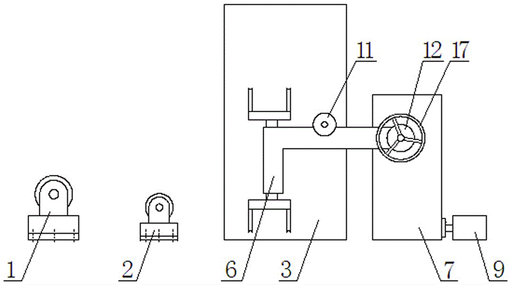
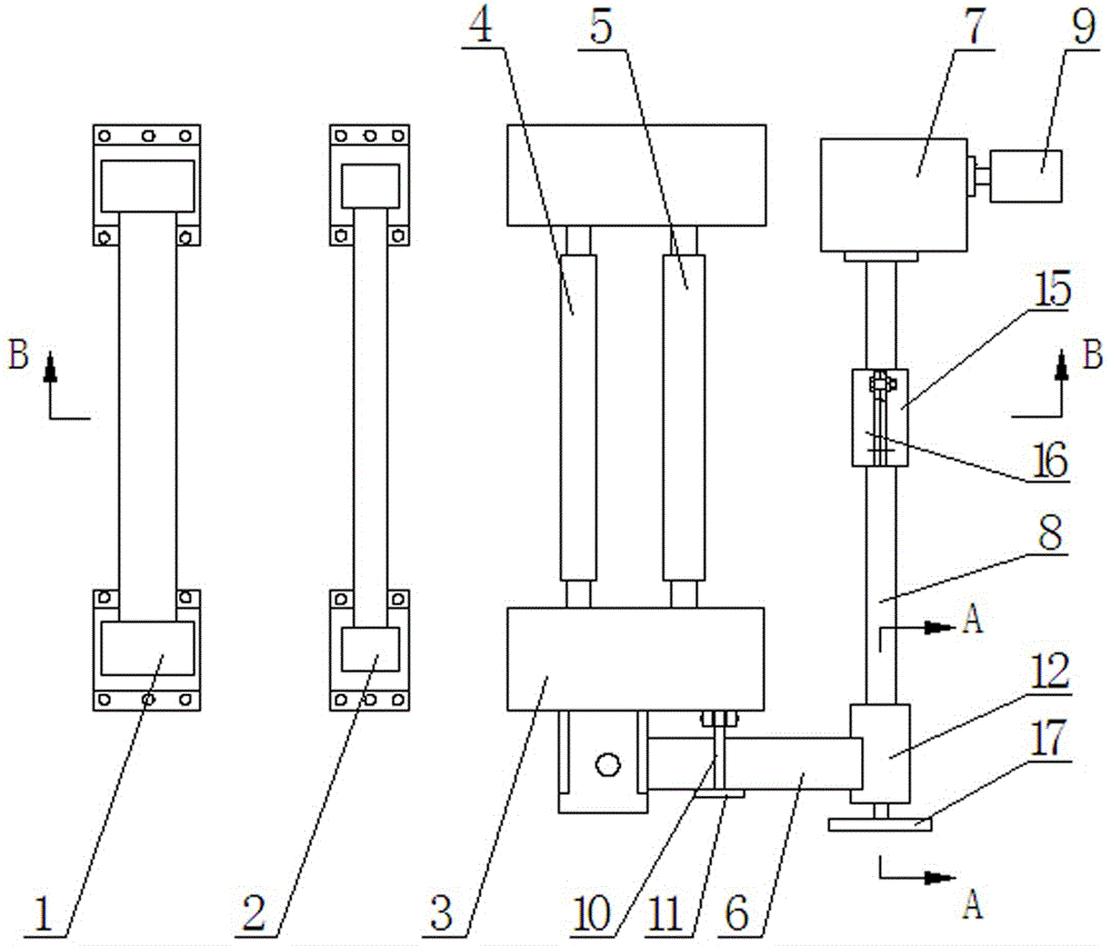
[0019] Such as Figure 2-5 As shown, a coil winding device includes an unwinding device I1, an unwinding device II2, a frame 3, a pulley I4 and a pulley II5, and it also includes a transmission device and a rotating frame 6, the pulley I4 and the pulley II5 is arranged in parallel and the guide wheel I4 is arranged on the top of the guide wheel II5, the two ends of the guide wheel I4 and the guide wheel II5 are rotated and installed on the frame 3, and the unwinding device I1 and the unwinding device II2 are arranged on the frame 3 On one side, the unwinding device II2 is arranged between the unwinding device I1 and the frame 3, and the transmission device is arranged on the other side of the frame 3, and the transmission device is composed of a reduction box 7, a transmission shaft 8 and a motor 9, ...


PUM


Abstract

The invention discloses a coil winding device. The coil winding device comprises an unwinding device I (1), an unwinding device II (2), a rack (3), a running wheel I (4) and a running wheel II (5), and further comprises a transmission device and a rotary frame (6), wherein the unwinding device I (1) and the unwinding device II (2) are arranged on one side of the rack (3); the short edge of the rotary frame (6) is perpendicular to the running wheel I (4); the two ends of the short edge of the rotary frame (6) are hinged to the rack (3); a limit device is composed of a limit rod (10) and a baffle (11); the baffle (11) is perpendicular to the limit rod (10) and arranged at the other end of the limit rod (10); a threaded hole (14) is formed inside a supporting base (12); the other end of a transmission shaft (8) abuts against the top of a threaded rod (13); the transmission shaft (8) is parallel to the running wheel I (4). The coil winding device has the advantages of being compact in structure and high in coil winding precision, workers can take out coils conveniently, and labor capacity of workers is saved.

Description

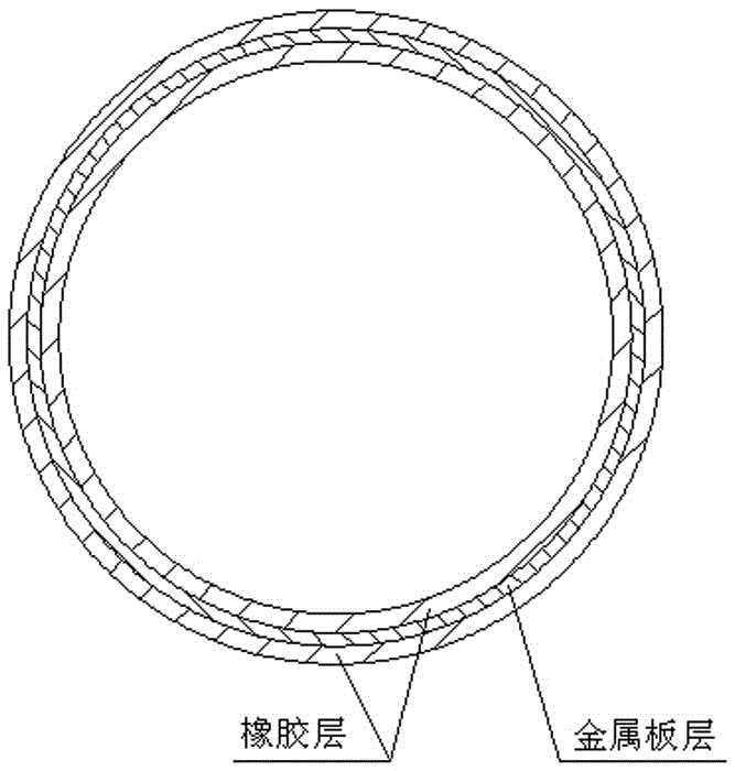
technical field [0001] The invention relates to the technical field of coil winding, in particular to a coil winding device. Background technique [0002] Coils used in high voltage wires are metal plates sandwiched between two layers of rubber, such as figure 1 A cross-sectional view of the coil is shown, and the rubber layer is used to prevent static electricity from the coil. At present, most coil production industries usually complete the winding of the coil manually. Before winding, the rolled rubber is unrolled in the workshop, and then the rolled metal plate is unrolled and covered on the rubber, and then another roll is rolled The rubber is unfolded and covered on the metal plate, and finally only the three-layer material is rolled up to make a coil for high-voltage wires. This processing method undoubtedly increases the workload of workers and wastes the space in the workshop. The disadvantage of lower yield. [0003] At present, the existing coil winding device ...

Claims


Application Information

Patent Timeline
Patent Type & Authority Patents(China)
IPC IPC(8): H01F41/061H01F41/082F16H57/023
Inventor 张明奎饶云金祝伟张力
Owner SICHUAN PROVINCE KUWAIT ELECTRICAL
Learn More