
Transmission type double-station punching machine with crank connecting rod structure

A crank connecting rod and transmission technology, applied in the field of machinery, can solve the problems of increased device size and cost, low working pressure, etc., and achieve the effect of compact structure, large output force and high transmission efficiency

Inactive Publication Date: 2014-08-20
SUZHOU POLYTECHNIC INST OF AGRI
View PDF4 Cites 10 Cited by
  • Summary
  • Abstract
  • Description
  • Claims
  • Application Information

AI Technical Summary

Problems solved by technology

However, the disadvantage of pneumatic transmission is that the working pressure is relatively low, generally around 0.5Mpa.
In some occasions that require a large output force, it will cause an increase in the size and cost of the device

Method used


Image

  • Transmission type double-station punching machine with crank connecting rod structure

Examples


Embodiment Construction

[0018] Specific embodiments of the present invention will be further described in detail below.

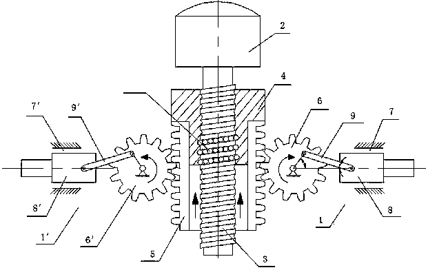
[0019] Such as figure 1 As shown, a transmission type double-station stamping machine adopting a crank-connecting rod structure of the present invention includes a machine tool (not shown) and two stamping stations 1, 1'. Two of the stamping stations 1, 1' are arranged symmetrically. However, according to the design concept of the present invention, multiple stamping stations can be arranged on one side or multiple groups of symmetrically arranged stamping stations can be arranged. A motor 2 is arranged on the machine tool, the output shaft of the motor 2 is coaxially connected with a lead screw 3 , and a nut 4 is threaded on the lead screw 3 . In this embodiment, a double-sided rack is socketed on the nut 4 , that is, a sleeve structure, and racks 5 are arranged on both sides thereof. The machine tool is also provided with two gears 6, 6' which mesh with the rack 5 respectively...


PUM


Abstract

The invention discloses a transmission type double-station punching machine with a crank connecting rod structure. The transmission type double-station punching machine with the crank connecting rod structure comprises a machine tool and two punching stations. The transmission type double-station punching machine with the crank connecting rod structure is characterized in that the machine tool is provided with a motor, an output shaft of the motor is coaxially connected with a lead screw which is in threaded connection with a nut in a sleeved mode, two racks are fixedly connected to the nut in the length direction of the lead screw, and two gears meshed with the two racks respectively are symmetrically arranged on the machine tool with the lead screw as the symmetry axis; the two punching stations are symmetrically arranged on the two sides of the lead screw with the lead screw as the symmetry axis, each punching station is provided with a sliding groove which is internally and movably provided with a plunger chip sliding block, the plunger chip sliding blocks are connected to the eccentric positions of the gears through hinged rods, and the gears and the plunger chip sliding blocks are hinged to the hinged rods. By means of the mode of synchronous punching of the two stations, production efficiency is greatly improved, the gravity center is low, stability is good, no pollution is produced, and the output force is large.

Description

technical field [0001] The invention belongs to the field of machinery, and relates to a transmission type double-station stamping machine adopting a crank connecting rod structure, in particular to a horizontal numerically controlled double-station stamping machine. Background technique [0002] At present, the traditional mechanical stamping machines are all vertical. On a vertical stamping machine, it is difficult to realize double-station stamping or multi-station stamping, and a CNC workbench is often required; the double-station vertical stamping with a CNC workbench is more complicated in structure, and the rigidity of the workbench Poor; in addition, the cost of the whole system is relatively high. Modern manufacturing, especially the manufacture of electronic appliances, communications and other products, has an increasingly urgent demand for high-efficiency, low-power automatic stamping machines, and traditional mechanical stamping machines are obviously unable to...

Claims


Application Information

Patent Timeline
IPC IPC(8): B30B1/06B30B15/26
Inventor 吴凡秦培亮夏春风钟康民
Owner SUZHOU POLYTECHNIC INST OF AGRI
Learn More