
Capillary tube throttling dynamic pressure and static pressure mixed bearing used for heavy roll grinder grinding spindle

A roll grinder and hybrid bearing technology, which is applied to the parts of grinding machine tools, grinding/polishing equipment, metal processing equipment, etc. And other issues

Inactive Publication Date: 2014-08-06
HUNAN UNIV +1
View PDF5 Cites 3 Cited by
  • Summary
  • Abstract
  • Description
  • Claims
  • Application Information

AI Technical Summary

Problems solved by technology

However, the bearing capacity of this structure is not large in the working state, the temperature rise of the bearing lubricating oil is high and the performance is greatly affected by the temperature rise, and the ability to resist the tilting of the main shaft is low; this may cause contact and collision between the axial edge of the bearing and the main shaft wear and tear

Method used


Image

  • Capillary tube throttling dynamic pressure and static pressure mixed bearing used for heavy roll grinder grinding spindle
  • Capillary tube throttling dynamic pressure and static pressure mixed bearing used for heavy roll grinder grinding spindle
  • Capillary tube throttling dynamic pressure and static pressure mixed bearing used for heavy roll grinder grinding spindle

Examples


Embodiment Construction

[0027] The technical solutions of the present invention will be further described below in conjunction with the drawings and embodiments.

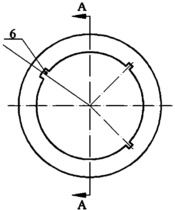
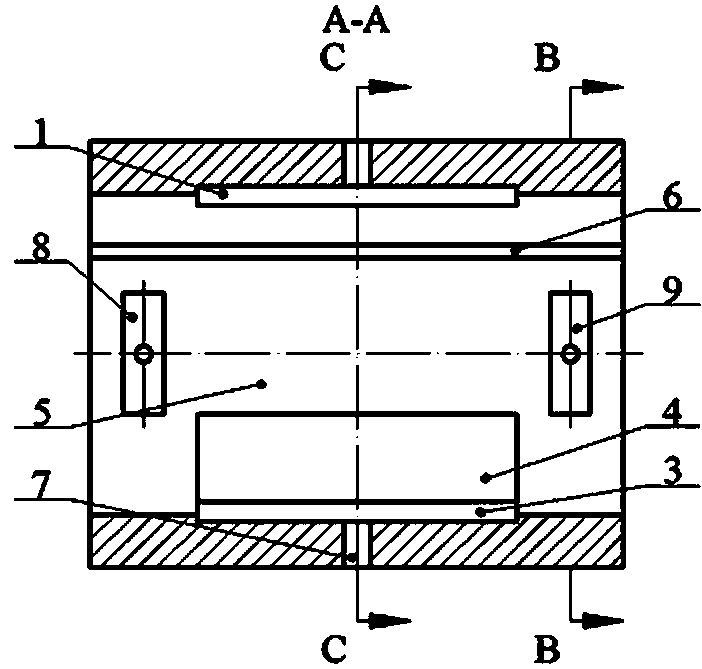
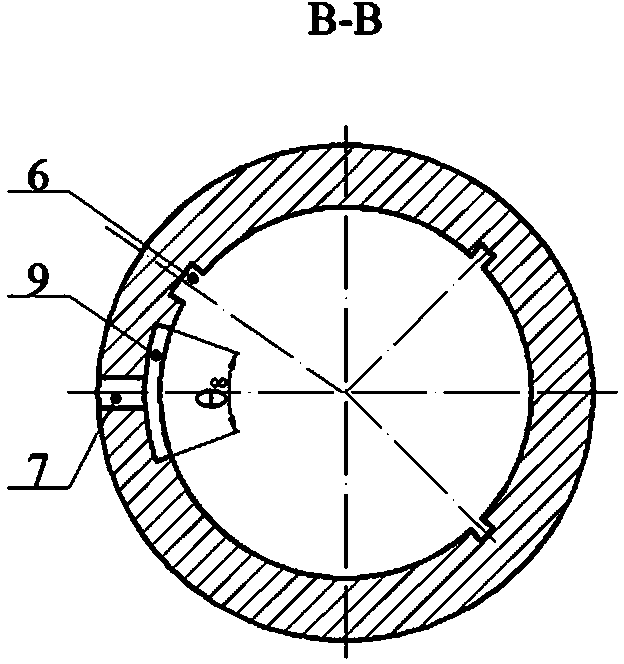
[0028] Such as Figure 1 to Figure 4 As shown, the structure of the capillary section hydrostatic hybrid bearing used on the main shaft of the grinding wheel of the heavy-duty roll grinder according to the present invention is that an upper static pressure chamber 1, a front static pressure chamber 2, and a lower static pressure chamber 3 are arranged on the bearing cavity wall , the left rear static pressure chamber 8 and the right rear static pressure chamber 9, the arc-shaped shallow chamber 4, the dynamic pressure chamber 5, three axial oil return grooves 6, and the oil inlet hole 7; the upper static pressure chamber 1 and the lower The static pressure chamber 3 is a pair of opposed oil chambers, and the centers of the two oil chambers are located on the vertical line a of the bearing; the center of the front static pressure chamber 2 ...


PUM


Abstract

A capillary tube throttling dynamic pressure and static pressure mixed bearing used for a heavy roll grinder grinding spindle comprises five static pressure cavities, an arc-shaped shallow cavity and three axial oil return tanks. The upper static cavity and the lower static cavity form a pair of oil containing cavities and are located on the perpendicular line of the bearing. The center of the front static pressure is located on the right of the horizontal line of the bearing and is close to a ground workpiece. The front static pressure cavity is arranged opposite to the left rear static pressure cavity and the right rear static pressure cavity. The horizontal center line of the front static pressure cavity, the horizontal center line of the left rear static pressure cavity and the horizontal center line of the right rear static pressure cavity are in the same horizontal plane. The left rear static pressure cavity and the right rear static pressure cavity are distributed in a central symmetry mode in the width direction of the bearing. A dynamic pressure cavity is the portion, except for the left rear static pressure cavity and the right rear static pressure cavity, of a dynamic pressure oil sealing face. The three axial oil return tanks are arranged at the upper end and the lower end of the front static pressure cavity and the left side of the upper static pressure cavity respectively. The five static pressure cavities are communicated with corresponding oil inlets (7) respectively. The arc-shaped shallow cavity is arranged between the lower static pressure cavity and the dynamic pressure cavity. The requirement for selection of the size of a capillary tube throttle exits. It is ensured that the spindle has high bearing capacity and low temperature rise at a high speed. The spindle has the anti-inclination capacity.

Description

technical field [0001] The present invention relates to a bearing, and further refers to a capillary section hydrostatic hybrid bearing used for the main shaft of a grinding wheel of a heavy-duty roll grinder. It has high bearing capacity, rigidity, rotation accuracy and low temperature rise, and also has a certain ability to resist the inclination of the main shaft. Background technique [0002] At present, more and more dynamic and static pressure bearings are used in the grinding wheel spindle of the roll grinder. With the gradual development of roll grinding machines in the direction of high efficiency, heavy load, high speed, and high precision, the dynamic and static pressure bearings in the grinding wheel spindle are required to have high load capacity, high rigidity, low bearing performance affected by lubricating oil temperature rise, and strong spindle tilt resistance. At present, the dynamic and static pressure bearing structure of the grinding wheel spindle of t...

Claims


Application Information

Patent Timeline
IPC IPC(8): B24B41/04
CPCB24B41/04
Inventor 郭力胡靖曹姗
Owner HUNAN UNIV
Learn More