Copper slag separation equipment

A technology of separation equipment and separator, applied in magnetic separation, solid separation, grain processing, etc., can solve the problems of flotation tailings index increase, construction difficulty, grinding efficiency reduction, etc., to maintain technical parameters and installation The size remains unchanged, the on-site installation is convenient and simple, and the effect of improving the metal recovery rate

Inactive Publication Date: 2014-07-30
尤廷晏
View PDF7 Cites 0 Cited by
  • Summary
  • Abstract
  • Description
  • Claims
  • Application Information

AI Technical Summary

Problems solved by technology

[0003] (1) With the progress of production, the wear and tear of the pump increases and the service efficiency decreases. The maintenance period changes from 120 days to 90 days. In serious cases, the pump is blocked and must be temporarily stopped for maintenance, which restricts the grinding production;
[0004] (2) The continuous circulation and accumulation of large particles of copper in the ball mill caused the reduction of grinding efficiency, and the unit processing capacity of the mill dropped from 5t / h to 4.85t / h, and in severe cases it was less than 4.7t / h;
[0005] (3) Due to the continuous circulation of bright copper, part of the too finely ground bright copper enters the flotation process together with the pulp, and the amount of flotation reagents increases from 150g / t to 180g / t, which is not conducive to the recovery of the target minerals , causing the flotation tailings index to increase by about 0.04%
However, if magnetic separation equipment is added before ore grinding, the site space requirements are high, the construction is difficult, the cost is high, and it will affect the existing process flow and technical parameters, so it is unreasonable to use magnetic separation equipment before ore grinding

Method used


Image

  • Copper slag separation equipment
  • Copper slag separation equipment
  • Copper slag separation equipment

Examples


specific Embodiment approach

[0019] The specific embodiment: the specific embodiment of the present invention is described in detail below in conjunction with accompanying drawing:

Embodiment

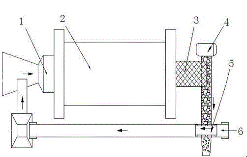
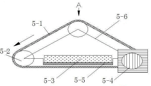
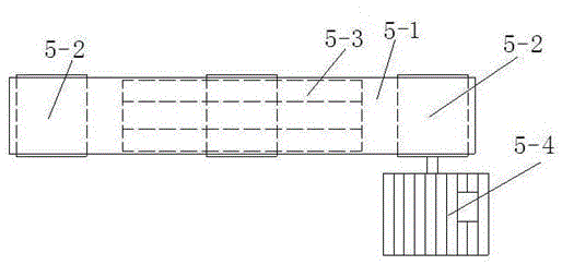
[0020] Embodiment: a kind of slag copper separation equipment (referring to Figure 1-Figure 3 ), it includes a base, the base is respectively connected to the ball mill 2, electric screen 4, slag copper separator 5, ore feeding belt 6 through the bracket, and the two ends of the ball mill 2 are respectively connected to the feed port 1, the cylindrical screen 3, and the cylindrical screen 3 Connect the electric sieve 4, the slag copper separator 5 is arranged on the top of the electric sieve 4, the electric vibrating screen 4 is arranged on the top of the ore feeding belt 6, and the ore feeding belt 6 is connected to the feed port 1. The slag-copper separator 5 comprises a triangular support 5-6, and the three corners of the triangular support 5-6 are respectively connected with 3 rollers 5-2, and the 3 rollers 5-2 are provided with a triangular belt 5-1, and the triangular support 5-6 A tray 5-5 is arranged on the tray 5-5, and a powerful magnet 3 with a magnetic induction i...


PUM

PropertyMeasurementUnit
magnetic flux densityaaaaaaaaaa
separationaaaaaaaaaa

Abstract

The invention discloses copper slag separation equipment. The copper slag separation equipment comprises a pedestal; the pedestal is characterized in that: the pedestal is connected with a ball mill (2), an electric sieve (4), a copper slag separator (5), an ore delivery belt (6) via supports respectively; the two ends of the ball mill (2) are connected with a feed inlet (1) and a cylinder sieve (3) respectively; the cylinder sieve (3) is connected with the electric sieve (4); the copper slag separator (5) is arranged above the electric sieve (4); the electric sieve (4) is arranged above the ore delivery belt (6); the ore delivery belt (6) is connected with the feed inlet (1); the copper slag separator (5) comprises a triangle bracket (5-6); the three angles of the triangle bracket (5-6) are connected with three idler wheels (5-2) respectively; the three idler wheels (5-2) are provided with a triangle belt (5-1); the triangle bracket (5-6) is provided with a tray (5-5); the tray (5-5) is provided with a powerful magnet (3); and one of the idler wheels (5-2) is connected with a motor. The copper slag separation equipment is simple in structure, low in cost, and short in installation time; the volume can be adjusted based on production demands; field installation is convenient; and the copper slag separation equipment is suitable for large area popularization.

Description

Technical field: [0001] The invention relates to a slag-copper separation device, which belongs to the technical field of slag-copper separation in the grinding process. Background technique: [0002] At present, the existing beneficiation process is two-stage open-circuit crushing, two-stage continuous grinding, and one-coarse, two-fine and three-sweeping separation processes. Affected by the smelting process, the blowing slag has strong magnetism and contains more large particles of bright copper. Due to the good ductility of metal copper, it is not easy to grind finely, resulting in the continuous circulation and accumulation of large particles of bright copper in the first-stage grinding process, resulting in the continuous circulation and accumulation of large-particle bright copper in the first-stage grinding system, and the grinding efficiency is reduced. Flotation Issues such as the increase in the dosage of chemicals and the increase in the grade of tailings have b...

Claims


Application Information

Patent Timeline
Patent Type & Authority Applications(China)
IPC IPC(8): B02C23/14B03C1/16
Inventor 尤廷晏宫兆庆韩立忠尹浩徐风
Owner 尤廷晏
Why Eureka
Try Eureka