
Image forming apparatus

An image and image flow technology, which is applied to the electric recording process using the charge pattern, the equipment for the electric recording process using the charge pattern, and the electric recording technique, etc. It can solve the problem of image quality degradation, inability to maintain the potential, and inability to maintain the surface of the photoreceptor drum. Maintain the charge and other issues to achieve the effect of extending execution time, shortening execution time, and shortening waiting time

Active Publication Date: 2014-07-23
COPYER
View PDF7 Cites 1 Cited by
  • Summary
  • Abstract
  • Description
  • Claims
  • Application Information

AI Technical Summary

Problems solved by technology

Therefore, when an image is formed, the charge caused by the charging of the charging device cannot be retained on the surface of the photoreceptor drum, and the potential cannot be maintained.
As a result, an image that flows through as a whole is formed, which is a major cause of image quality degradation.

Method used


Image

  • Image forming apparatus
  • Image forming apparatus
  • Image forming apparatus

Examples


Embodiment approach 1

[0040] Embodiments of the present invention will be described in detail below. The scope of the present invention is not limited to the device configuration, components, dimensions, materials, shapes, and other relative arrangements of components described in the following embodiments unless otherwise specified.

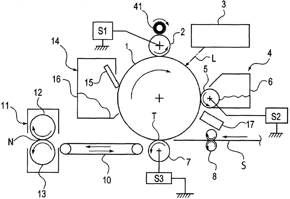
[0041] figure 1 is a schematic diagram illustrating a schematic configuration of an image forming apparatus. The image forming apparatus is an electrophotographic image forming system using a drum-type electrophotographic photoreceptor (hereinafter referred to as a photoreceptor drum) 1 as a rotatable image carrier for forming an electrostatic latent image. device.

[0042] The photoreceptor drum 1 is rotatably supported around the drum axis, and is driven by a drive mechanism (not shown). figure 1 It is driven to rotate at a specified speed in the direction of the arrow (clockwise). The image forming unit that forms a toner image on the photoreceptor drum 1 incl...

Embodiment approach 2

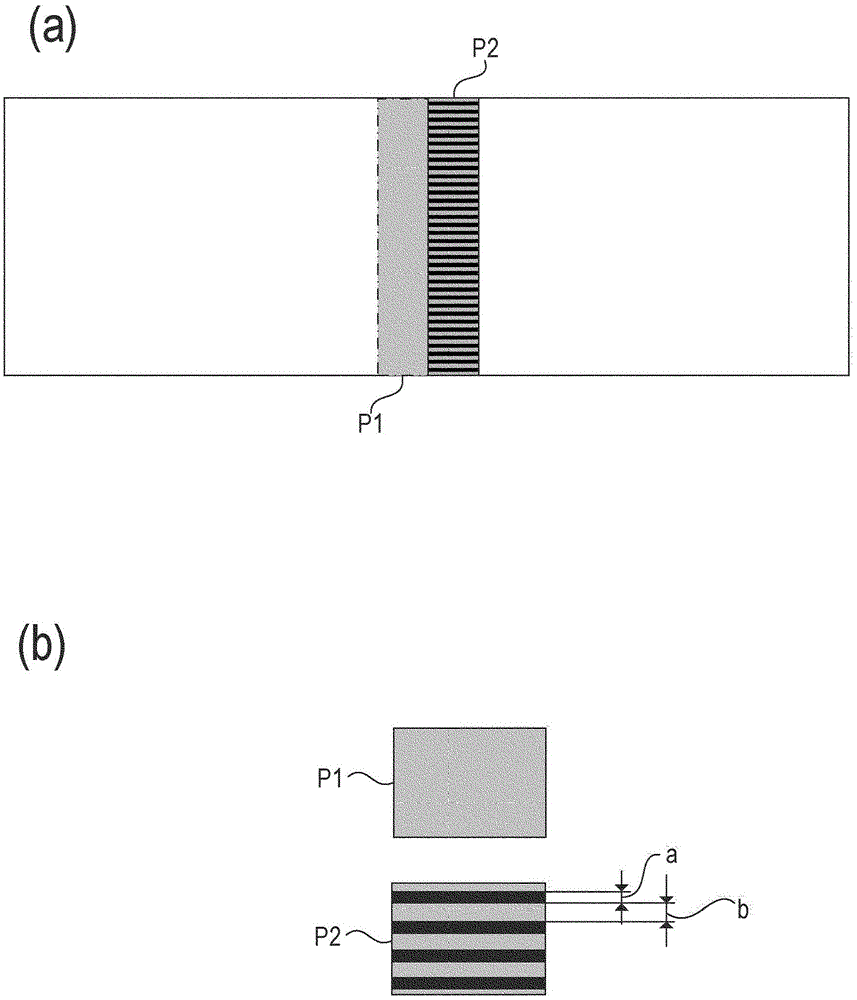
[0103] according to Figure 8(a) and (b) describe the pattern images P3 and P4 for image flow detection in this embodiment. Figure 8 (a) and (b) show an example of the pattern images P3 and P4 for image flow detection of this embodiment. Figure 8 (a) is a developed view of the peripheral surface of the photoreceptor drum 1, Figure 8 (b) is an enlarged image diagram of the pattern images P3 and P4 for image flow detection.

[0104] like Figure 8 As shown in (a), for example, in the approximate center position of the photosensitive drum 1 in the main scanning direction, at least an amount corresponding to at least one round of the photosensitive drum 1 is formed in the circumferential direction (sub-scanning direction) of the photosensitive drum 1 . Pattern images P3 and P4 for image flow detection. The reason why the pattern images P3 and P4 for image flow detection need to be at least as long as one turn of the photoreceptor drum 1 is to reliably detect the occurrence ...


PUM


Abstract

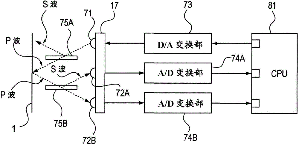
The present invention aims to precisely detect an image flow generation level and reliably recover image flow. An image forming apparatus is provided with an image forming part forming a color toner image on a photoreceptor drum; an intensity sensor detecting the intensity of the color toner image of the photoreceptor drum; and a control part for determining the surface state of the photoreceptor drum according to the detecting result of the intensity sensor, wherein the image forming part forms a first pattern image and a second pattern image different from the first pattern image on the surface of the photoreceptor drum, and the control unit determines the intensity of the first pattern image and the second pattern image formed on the surface of the photoreceptor drum and determines the surface state of the photoreceptor drum according to the detecting results of the intensity sensor.

Description

technical field [0001] The present invention relates to an image forming apparatus that performs an image flow restoration operation of cleaning the surface of an image carrier to restore the image flow. Background technique [0002] Conventionally, in an electrophotographic image forming apparatus, a photoreceptor drum is charged by a charging device, exposed by an exposure device, and an electrostatic latent image is formed in accordance with image data. The electrostatic latent image is developed with a toner by a developing device, and the toner image is transferred to a sheet and then fixed to form an image. In image formation, a phenomenon called image streaming sometimes occurs. [0003] The phenomenon called image streaming will be described. The charging device charges the photoreceptor drum with a relatively large voltage by discharging or the like. Ozone, nitrogen oxides, etc. are generated by a high-voltage discharge phenomenon, and adhere to the photosensitiv...

Claims


Application Information

Patent Timeline
Patent Type & Authority Applications(China)
IPC IPC(8): G03G15/00
Inventor 宫本明典河合信太朗
Owner COPYER
Learn More