Eureka AIR delivers breakthrough ideas for toughest innovation challenges, trusted by R&D personnel around the world.

Self-adaptation ionic current detecting device

A technology of ionic current and detection device, applied in spark ignition controller, engine components, machine/engine, etc., can solve the problem of affecting the waveform of ionic current signal, and achieve the effect of high accuracy

Inactive Publication Date: 2014-07-23
TONGJI UNIV
View PDF4 Cites 6 Cited by
  • Summary
  • Abstract
  • Description
  • Claims
  • Application Information

AI Technical Summary

Problems solved by technology

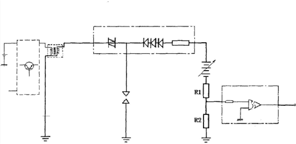
Since the spark plug is used as the ion current sensor, the ignition discharge interference will inevitably significantly affect the ion current signal waveform

Method used


Image

  • Self-adaptation ionic current detecting device
  • Self-adaptation ionic current detecting device
  • Self-adaptation ionic current detecting device

Examples


Embodiment Construction

[0027] The present invention will be further described below in conjunction with the embodiments shown in the accompanying drawings.

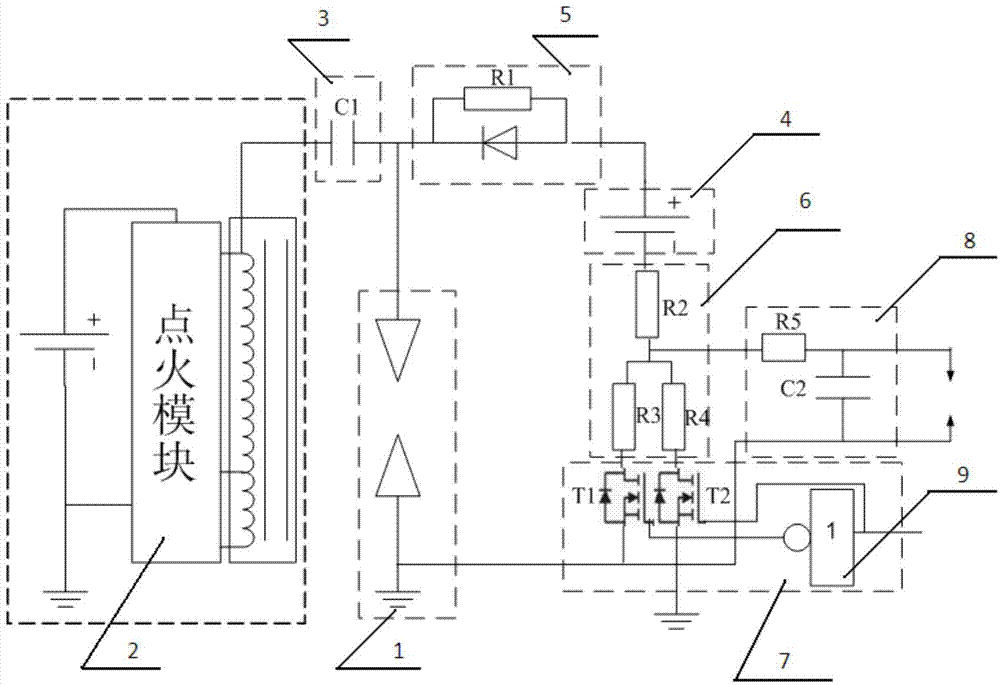
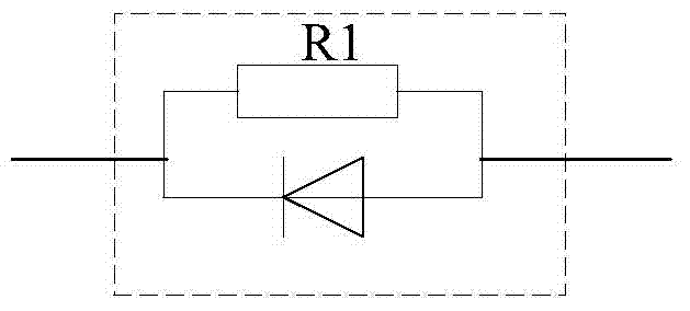
[0028] The present invention proposes an adaptive ion current detection device capable of adaptive adjustment according to the engine combustion mode, and capable of maintaining high accuracy under the SI / HCCI multi-mode of the engine. The device includes an isolation capacitor 3, an external bias power supply 4, a high-voltage isolation module 5, a voltage divider circuit 6, a variable resistance circuit 7, and a signal preprocessing circuit 8. The circuit schematic diagram is as follows figure 2 shown. Wherein, one end of the isolation capacitor 3 is connected to the output end of the ignition module 2 of the engine, and the other end is connected to the input end of the spark plug 1 of the engine and the input end of the high-voltage isolation module 5, and the output end of the high-voltage isolation module 5 is connected to an external bi...


PUM


Abstract

The invention provides a self-adaptation ionic current detecting device which comprises an ignition isolation module, a high-voltage isolation module, a bias power supply module, a voltage dividing module, a signal preprocessing module and a variable resistance module. One end of the ignition isolation module is connected with an ignition module of an engine, and the other end of the ignition isolation module is connected with the input end of an ignition plug of the engine and is connected with one end of the high-voltage isolation module. The other end of the high-voltage isolation module is connected with a positive electrode of the bias power supply module. A negative electrode of the bias power supply module is connected with one end of the voltage dividing module. The other end of the voltage dividing module is connected with the output end of the variable resistance module which is provided with an engine combustion mode control signal receiving end, and the output end of the voltage dividing module is connected with the input end of the signal preprocessing module. The self-adaptation ionic current detecting device can carry out effective isolation on interference from ignition, high voltage, a background and the like, self adaptation on engine SI / SCCI mode switching is achieved, and the ionic current of an internal combustion engine cylinder inner combustion state can be detected accurately and completely in real time.

Description

technical field [0001] The invention belongs to the technical field of internal combustion engines, and relates to a device for detecting the combustion state of the internal combustion engine. Background technique [0002] The combustion process of the engine depends on the comprehensive effects of the physics and chemistry of the mixture in the cylinder. In order to control the combustion process of the engine, a real-time feedback signal is needed to determine the combustion state. The ion current signal contains a large amount of information about combustion and operation in the cylinder of the engine. Through signal collection and processing, the required combustion information can be obtained and used for closed-loop control of the combustion process. The size of the ion current is related to the instantaneous local ion concentration, and the size of the local ion concentration depends on the ability of the combustion chemical reaction in the cylinder to generate ions ...

Claims


Application Information

Patent Timeline
Patent Type & Authority Applications(China)
IPC IPC(8): F02P17/12
Inventor 邓俊李理光曹银波胡宗杰吴志军
Owner TONGJI UNIV
Why Eureka
Eureka Blog
Learn More