A high-intensity carbon dioxide laser

A technology of carbon dioxide and lasers, which is applied in the field of lasers, can solve the problems of carbon dioxide laser damage, reduce the structural stability and use accuracy of carbon dioxide lasers, increase and other problems, achieve good cooling effect, avoid the effect of non-flowing cooling water, and not easy to damage

Active Publication Date: 2018-04-10
CHENGDU WEESON TECH
View PDF5 Cites 1 Cited by
  • Summary
  • Abstract
  • Description
  • Claims
  • Application Information

AI Technical Summary

Problems solved by technology

[0005] In the structure of the water-cooled tube and the discharge tube, the end of the water-cooled tube close to the anode electrode is fixedly connected to the gas storage tube and connected to the water outlet pipe, while the end of the water-cooled tube close to the cathode electrode is suspended and connected to the water inlet pipe, so The water pipe and the water outlet pipe not only play the role of water in and out, but also support and fix the cooling water pipe and the discharge tube. Therefore, the current water-cooled pipe and the discharge tube are fixed at the In the gas storage tube; since the carbon dioxide laser has a slender structure, its water-cooled tube is also a slender structure, so that the water-cooled tube supported at both ends has a long span, and when it is stored, transported, and used, the carbon dioxide laser is usually They are all placed in a horizontal state, so the water-cooled pipe between the water inlet pipe and the water outlet pipe is bent due to the influence of its own gravity, resulting in a large degree of winding. The existence of this large disturbance not only reduces the carbon dioxide laser Structural stability and accuracy of use, especially during transportation, when the packing box is impacted, when the impact is transmitted to the carbon dioxide laser, the water cooling pipe between the water inlet pipe and the water outlet pipe will be further bent, and the winding degree will be further increased. Large, when the bending degree is too large, the water-cooled tube will be damaged and fractured, resulting in damage to the carbon dioxide laser

Method used


Image

  • A high-intensity carbon dioxide laser
  • A high-intensity carbon dioxide laser
  • A high-intensity carbon dioxide laser

Examples


Embodiment Construction

[0032] The present invention will be described in detail below with reference to the accompanying drawings.

[0033] In order to make the objectives, technical solutions and advantages of the present invention clearer, the present invention will be further described in detail below with reference to the accompanying drawings and embodiments. It should be understood that the specific embodiments described herein are only used to explain the present invention, but not to limit the present invention.

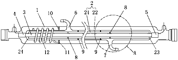
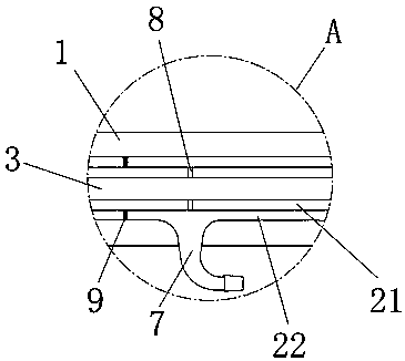
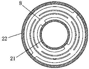
[0034] like Figure 1-3 The shown high-intensity carbon dioxide laser includes a gas storage tube 1, a water-cooled tube 2 and a discharge tube 3 that are sleeved from the outside to the inside in sequence, and the two ends of the discharge tube 3 are respectively provided with an anode electrode 4 and a cathode electrode 5. The air storage pipe 1 is provided with a water inlet pipe 6 and a water outlet pipe 7 which are connected to the water cooling pipe 2. The position where one...


PUM


Abstract

The present invention relates to the field of lasers, in particular to a high-intensity carbon dioxide laser, which includes a gas storage tube, a water-cooled tube and a discharge tube that are sequentially sleeved from outside to inside. The air pipe is provided with a water inlet pipe and an outlet pipe connected to the water-cooling pipe, and the distance between the position where one of the water inlet pipe and the water outlet pipe is connected to the water-cooling pipe is the distance from the end of the water-cooling pipe by the water-cooling pipe. 1 / 5~1 / 2 of the tube length. Compared with the laser in which the water inlet pipe and the water outlet pipe are respectively arranged at both ends of the water-cooled pipe, the laser of the present invention reduces the winding degree of the water-cooled pipe between the water inlet pipe and the water outlet pipe, and improves the structural stability and use accuracy of the carbon dioxide laser. The water-cooled tube is not easy to be damaged due to excessive bending, that is, the impact resistance of the water-cooled tube is improved, and the impact resistance of the carbon dioxide laser is also improved.

Description

technical field [0001] The invention relates to the field of lasers, in particular to a high-intensity carbon dioxide laser. Background technique [0002] Due to the relatively large power and high energy conversion efficiency of carbon dioxide lasers, the spectral lines are also relatively rich, and the laser output with dozens of spectral lines near 10 microns has been widely used in industry, military, medical, scientific research, etc. Applications. [0003] The current carbon dioxide laser usually includes a discharge tube, a water-cooling tube sleeved outside the discharge tube, a gas storage tube sleeved outside the water-cooled tube, a cathode electrode and an anode electrode respectively disposed at both ends of the discharge tube, and a gas storage tube. The output window and the reflection window at the end, the reflection window includes the reflection lens and the cooling device for the reflection lens, the output window includes the output lens and the cooling...

Claims


Application Information

Patent Timeline
Patent Type & Authority Patents(China)
IPC IPC(8): H01S3/041
Inventor 殷卫援
Owner CHENGDU WEESON TECH
Why Eureka
Try Eureka