Combinational logic circuit capable of maintaining duty ratio

A combination logic circuit and duty cycle technology, applied in the direction of electrical digital data processing, special data processing applications, instruments, etc., can solve disadvantages and other problems

Inactive Publication Date: 2014-07-09
BEIJING CEC HUADA ELECTRONIC DESIGN CO LTD
View PDF3 Cites 0 Cited by
  • Summary
  • Abstract
  • Description
  • Claims
  • Application Information

AI Technical Summary

Problems solved by technology

Therefore, if the synchronous circuit design structure with double-edge trigger is adopted, that is, there are figure 1 , figure 2 For the half-cycle path shown, the shortening of clock rise-to-fall half-cycle or fall-to-rise half-cycle, respectively, would be detrimental figure 1 , figure 2 The setup timing is closed

Method used


Image

  • Combinational logic circuit capable of maintaining duty ratio
  • Combinational logic circuit capable of maintaining duty ratio
  • Combinational logic circuit capable of maintaining duty ratio

Examples


Embodiment Construction

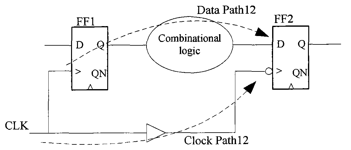
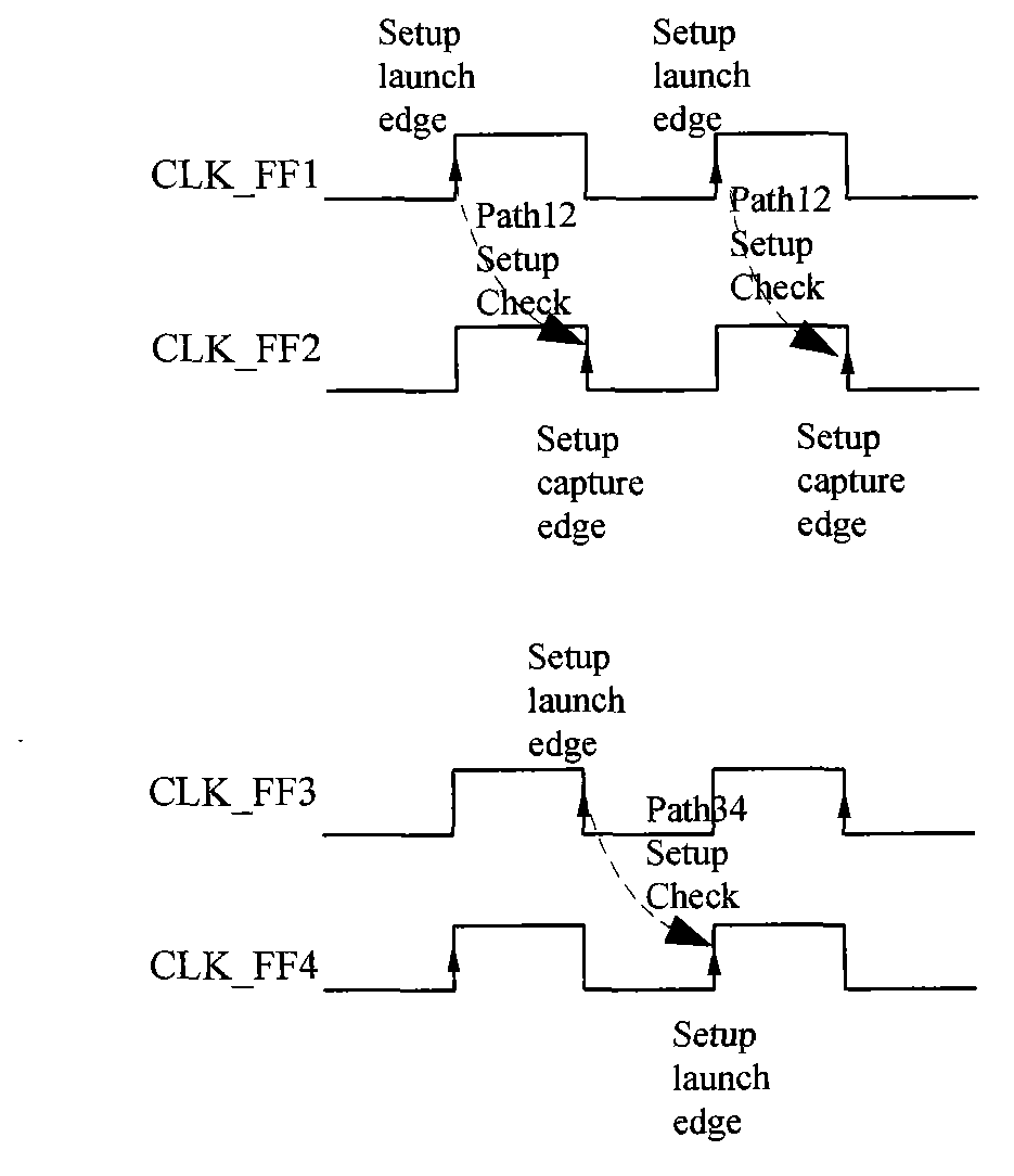
[0021] Due to the asymmetry of the rising edge and falling edge delay of the combinational logic device in the process library, the clock signal passes through Figure 4 The rising edge delay and the falling edge delay after the combination of the clock network shown in the logic device are not equal, which will cause the duty cycle of the trigger clock to deteriorate, which is not conducive to the timing convergence of the half-cycle path setup.

[0022] If the required logic provides the same logic cell with inverted output in the standard cell library, keep the duty cycle logic implementation structured as Figure 5 shown. Figure 5 Indicates that two identical outputs are inversely connected in series, such as Figure 8 , Figure 9 , to realize the AND or OR logic that maintains the duty cycle, then connect two NAND gates or NOR gates with the same driving capability in series. Its principle of maintaining the duty cycle is as Figure 7 As shown, the rising edge delay ...


PUM


Abstract

The invention discloses a combinational logic circuit capable of maintaining the duty ratio. The circuit structure has the advantages of capable of maintaining the duty ratio of input and output signals. The circuit is applicable to the field of circuit design with high requirements for input and output signal duty ratio consistency, for example, the field of double-edge sampling synchronous circuit design. By means of the combinational logic circuit, the clock path duty ratio in integrated circuits can be maintained, the combinational logic clock signal duty ratio is in accordance with that of input signals, and the digital circuit setup time in integrated circuits can meet the convergence requirement easily.

Description

technical field [0001] The invention is applied to the field of synchronous circuit design which adopts double-edge trigger and requires high clock signal duty cycle. Background technique [0002] Synchronous digital integrated circuit system In the current digital integrated circuit design, the method of synchronous circuit is the most intuitive and reliable method in digital design. The so-called synchronization means that all flip-flops in this circuit system are controlled by the clock of the same clock domain. Synchronous circuits contain three main circuit structures: combinational logic, sequential logic, and clock distribution networks. Half-cycle sequential circuit design such as figure 1 , figure 2 as shown, figure 1 is the half-cycle path from the rising edge to the falling edge of the clock, figure 2 It is the half-cycle path from the falling edge of the clock to the rising edge. The setup time of the circuit structure plays a key role in whether the circ...

Claims


Application Information

Patent Timeline
Patent Type & Authority Applications(China)
IPC IPC(8): G06F17/50
Inventor 杨逸轩王延斌蒙卡娜包乌日吐
Owner BEIJING CEC HUADA ELECTRONIC DESIGN CO LTD
Why Eureka
Try Eureka