A Delay Locked Loop Circuit Realizing Duty Cycle Correction and Delay Locking Simultaneously

A delay-locked loop and delay-locked technology, applied in the direction of electrical components, automatic power control, etc., can solve the problems of clock duty cycle distortion, complex circuit, large scale, etc., to achieve the effect of simplifying DLL and DCC circuits

Active Publication Date: 2018-08-14
XI AN UNIIC SEMICON CO LTD
View PDF5 Cites 0 Cited by
  • Summary
  • Abstract
  • Description
  • Claims
  • Application Information

AI Technical Summary

Problems solved by technology

[0011] Disadvantages of traditional DLL and DCC circuits: In this structure, it can be seen that the DLL and DCC circuits are implemented by independent circuits, and the circuits are relatively complex and large in scale
And although the input clock passes through the DLL and DCC circuit to obtain a synchronous clock with a duty ratio of 50%, when the DCC output clock is transmitted to the clock transmission circuit, due to the influence of objective factors such as process temperature, the transmission of the clock will produce a duty cycle Ratio distortion, so that the final output clock of the whole system can no longer guarantee the ideal 50% duty cycle

Method used


Image

  • A Delay Locked Loop Circuit Realizing Duty Cycle Correction and Delay Locking Simultaneously
  • A Delay Locked Loop Circuit Realizing Duty Cycle Correction and Delay Locking Simultaneously
  • A Delay Locked Loop Circuit Realizing Duty Cycle Correction and Delay Locking Simultaneously

Examples


Embodiment Construction

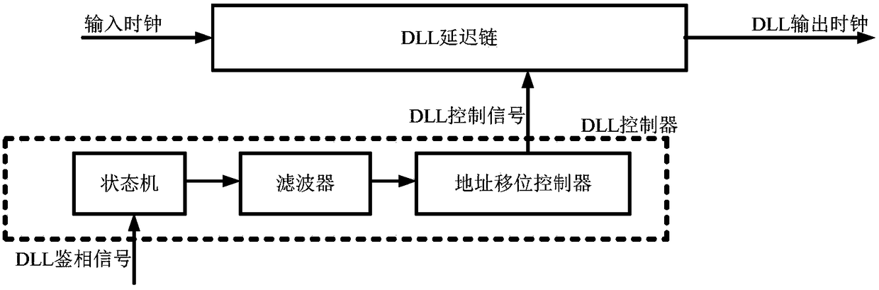
[0027] see image 3 As shown, the present invention realizes a delay-locked-loop circuit for duty ratio correction and delay-locked phase at the same time. The DLL circuit and the DCC circuit are combined, and the duty ratio detection circuit of the clock is added on this basis, which simplifies the DLL and DCC circuits, and can ensure that the final output clock of the system is 50% duty cycle.

[0028] The present invention is a delay phase-locked loop circuit that simultaneously realizes duty ratio correction and delay phase locking, referred to as a DLLDCC circuit, including a DLLDCC delay chain, a DLLDCC controller, a DLL phase detector, a duty ratio detection circuit, a DLL feedback circuit and a clock transmission circuit.

[0029] The input clock is connected to the input end of the DLLDCC delay chain and the first input end of the DLL phase detector; the output end of the DLLDCC delay chain is connected to the input end of the clock transmission circuit and the input...


PUM


Abstract

The invention discloses a delay locked loop circuit for simultaneously realizing duty cycle correction (DCC) and delay locked loop (DLL). The delay locked loop circuit comprises a DLLDCC delay chain, a DLLDCC controller, a DLL phase detector, a duty cycle detection circuit and a DLL feedback circuit; an input clock is connected to the input end of the DLLDCC delay chain and the first input end of the DLL phase detector; the input end of the DLL feedback circuit is connected to an output clock output by the DLLDCC delay chain; the output end of the DLL feedback circuit is connected to the second input end of the DLL phase detector; the output end of the DLL phase detector is connected to the DLLDCC delay chain via the DLLDCC controller; the input end of the duty cycle detection circuit is connected to a final output clock, and the output end of the duty cycle detection circuit is connected to the DLLDCC controller. The traditional DLL circuit structure is improved, so that the delay locked loop circuit simultaneously realizes DLL and DCC functions, greatly simplifies DLL and DCC circuits and can ensure that the duty cycle of the final output clock is 50%.

Description

technical field [0001] The invention relates to the technical field of delay-locked loop and duty cycle correction, in particular to a delay-locked loop circuit for realizing duty cycle correction and delay phase-locking simultaneously. Background technique [0002] Delay Locked Loop (DLL) and Duty Cycle Correction (DCC) circuits are widely used in microprocessors, memory interfaces, interfaces between chips, and clock distribution networks in large-scale integrated circuits. DLL is used for clock synchronization to solve the clock skew problem, so that the clock delay within the chip or between chips has enough margin, thereby improving the timing function of the system. DCC is used to adjust the duty cycle of the clock (usually 50%), so that both the rising and falling edges of the clock can be used to sample data, thereby increasing the transmission rate of the signal. DLL circuits and DCC circuits are often used together in various application systems, such as semicondu...

Claims


Application Information

Patent Timeline
Patent Type & Authority Patents(China)
IPC IPC(8): H03L7/083
CPCH03L7/083
Inventor 郭晓锋
Owner XI AN UNIIC SEMICON CO LTD
Why Eureka
Try Eureka