Direct-current motor speed-regulating system with voltage regulation function

A technology for DC motors and speed control systems, applied in the field of speed control systems, can solve the problems of poor output voltage stability and low duty cycle of output square waves, and achieve the effects of accurate control, strong practicability, and simple structure

Inactive Publication Date: 2018-05-25
四川新驱科为科技有限公司
View PDF0 Cites 0 Cited by
  • Summary
  • Abstract
  • Description
  • Claims
  • Application Information

AI Technical Summary

Problems solved by technology

[0004] The purpose of the present invention is to overcome the defect that the pulse width modulator used in the existing DC motor not only has a low duty ratio of the output square wave, but also has poor stability of the output voltage, and provides a DC motor with a voltage regulation function. system

Method used


Image

  • Direct-current motor speed-regulating system with voltage regulation function

Examples


Embodiment

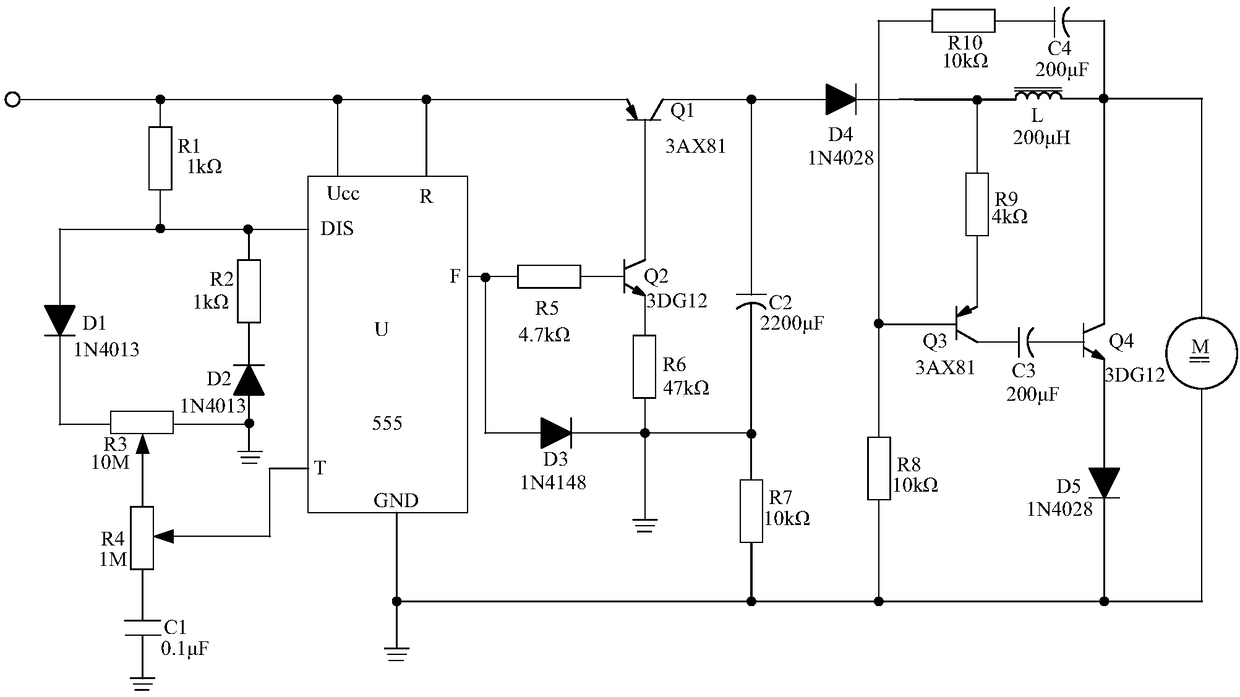
[0016] Such as figure 1 As shown, the present invention discloses a DC motor speed control system with a voltage regulation function, including a control chip U, a pulse width modulation circuit connected to the UCC pin, the DIS pin and the T pin of the control chip U respectively, A three-manifold drive circuit connected to the R pin, F pin and GND pin of the control chip U, and a voltage regulating circuit connected to the three-manifold drive circuit; the GND pin of the control chip U is grounded .

[0017] The control chip U in this embodiment is preferably implemented by using the NE555 integrated chip with pulse generation function. The control chip U is combined with a pulse width modulation circuit to continuously adjust the duty ratio of the output pulse, that is, the pulse width It is fully adjusted without affecting the oscillation frequency of the control chip U, so that the duty cycle of the pulse reaches 99.99%.

[0018] Further, the pulse width modulation circ...


PUM


Abstract

The invention discloses a direct-current motor speed-regulating system with the voltage regulation function. The system is characterized by comprising a control chip U, a pulse width modulation circuit, an audion-driven circuit and a voltage regulating circuit, wherein the audion-driven circuit is connected with an R pin, an F pin and a GND pin of the control chip, and the voltage regulating circuit is connected with the audion-driven circuit. The system is simple in structure and high in practicability, the arranged pulse width modulation circuit can continuously adjust the duty ratio of output pulse, the pulse width is fully adjusted, the oscillation frequency can not be affected, the duty ratio of the pulse reaches 99.99%, thus it is ensured that the system can output the duty ratio ofhigh pulse, and the problem that the duty ratio of output square wave in the pulse width modulation circuit is very low is well solved.

Description

technical field [0001] The invention relates to a speed regulation system, in particular to a DC motor speed regulation system with voltage regulation function. Background technique [0002] A DC motor is a motor that converts DC electrical energy into mechanical energy, and is widely used in electric drive because of its good speed regulation performance. The DC motor achieves speed regulation through a pulse width modulator. The full name of the pulse width modulator is: Pulse Width Modulator, or PWM for short. The pulse width modulator changes the average current power on the load from 0-100% by changing the duty cycle of the output square wave, thereby changing the speed of the DC motor. [0003] However, the duty cycle of the output square wave of the pulse width modulator used in the existing DC motor is mostly about 50%, that is to say, the energy power output by the pulse width modulator is only about 50%. Therefore, the existing The pulse width modulator used in t...

Claims


Application Information

Patent Timeline
IPC IPC(8): H02P7/29
CPCH02P7/29
Inventor 王前明
Owner 四川新驱科为科技有限公司
Why Eureka
Try Eureka