A kind of oil cooler for high-power high-voltage electric vacuum device

A technology for vacuum devices and oil coolers, applied in electrical components, circuits, discharge lamps, etc., can solve the problems of the insulation distance making the structure difficult to compact, the insulation and heat dissipation effects are large, and the air heat conduction efficiency is low, so as to overcome the air cooling method. Insufficient, stable dielectric strength, stable and reliable device operation

Active Publication Date: 2016-08-03
SOUTHWESTERN INST OF PHYSICS
View PDF4 Cites 0 Cited by
  • Summary
  • Abstract
  • Description
  • Claims
  • Application Information

AI Technical Summary

Problems solved by technology

The cooling of traditional high-power electric vacuum devices generally adopts air-cooling. Although the structure of the air-cooling system is relatively simple, the heat conduction efficiency of air is low. Compared with oil cooling, its thermal conductivity is lower
In addition, air cleanliness, temperature, humidity and air pressure have a great influence on the insulation and heat dissipation of high-voltage electric vacuum devices, and the insulation distance makes it difficult to compact the structure

Method used


Image

  • A kind of oil cooler for high-power high-voltage electric vacuum device
  • A kind of oil cooler for high-power high-voltage electric vacuum device
  • A kind of oil cooler for high-power high-voltage electric vacuum device

Examples


Embodiment Construction

[0019] The present invention will be further described below in conjunction with the accompanying drawings and embodiments.

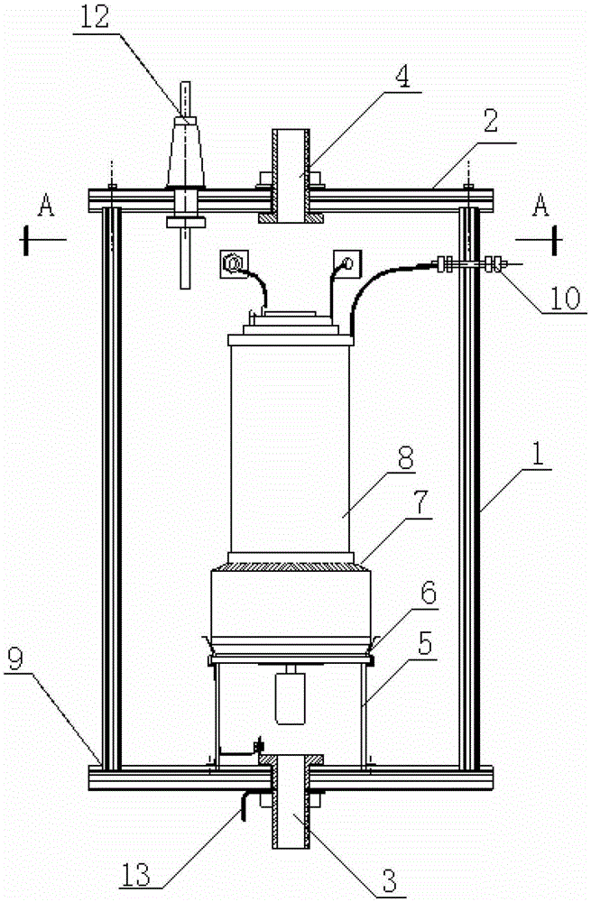
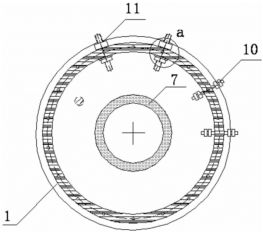
[0020] An oil cooler for high-power high-voltage electric vacuum devices such as figure 1 , figure 2 As shown, it is assembled by the following steps:

[0021] 1. First process the custom-made plexiglass or epoxy resin tube or plate into a blank, and the above two materials have been used in the device; then machine them into parts of the outer barrel of the oil cooler, including the side wall 1 , the base plate 9 and the cover plate 2, the base plate 9 and the cover plate 2 all have side wall grooves fixed with the side wall 1, and are respectively provided with holes for setting the oil inlet 3 and the oil outlet 4, and the holes are sealed with The oil inlet 3 and the oil outlet 4; the end of the side wall 1 is tapped, and the center line of the above holes coincides, and the screw connection can be used to compress and seal, similar to the flange...


PUM


Abstract

The invention discloses an oil cooler used for a high-power high-voltage vacuum device, which comprises a side wall (1), a cover plate (2), an oil inlet (3) and an oil outlet (4), an element tube seat (5), a metal spring fastener (6) and a bottom plate (9), wherein the side wall (1) has a hollow cylindrical structure; the bottom plate (9) and the cover plate (2) are disk-shaped; the side wall (1) and the bottom plate (9) are bonded in a matching mode and sealed to form an outer cylinder; the side wall (1) is in sealing connection with the cover plate (2); a rubber gasket is placed in the groove of the cover plate (2); both the groove of the cover plate (2) and the rubber gasket are provided with holes; the centers of the bottom plate (9) and the cover plate (2) are respectively provided with the holes of the oil inlet (3) and the oil outlet (4); the element tube seat (5) is fixed in a tube seat groove; the upper surface of the element tube seat (5) is provided with the metal spring fastener (6); and a plurality of line incoming and line outgoing terminals are arranged on the oil cooler. According to the oil cooler used for the high-power high-voltage vacuum device, better cooling efficiency can be achieved, and temperature rise can be controlled.

Description

technical field [0001] The invention belongs to the technical field of power supply cooling, and in particular relates to an oil cooler for high-power and high-voltage electric vacuum devices. Background technique [0002] The power supply system for the auxiliary heating of China Circulator No. 2 A (HL-2A) Tokamak device needs to modulate the pulse high-power high-voltage output. It is necessary to cool the high-power high-voltage tetrode (electric vacuum element) used in the output modulator of the power supply system, and the dissipation power of the anode of the element alone reaches more than 4kw. The cooling of traditional high-power electric vacuum devices generally adopts air-cooling. Although the structure of the air-cooling system is relatively simple, the heat conduction efficiency of air is low. Compared with oil cooling, its thermal conductivity is lower. In addition, air cleanliness, temperature, humidity and air pressure have a great influence on the insulati...

Claims


Application Information

Patent Timeline
Patent Type & Authority Patents(China)
IPC IPC(8): H01J7/24
Inventor 李飞镝王民宣伟民姚列英卜明南
Owner SOUTHWESTERN INST OF PHYSICS
Why Eureka
Try Eureka