Shutter type MEMS large-rotation-corner adjustable blazed grating light modulator and array thereof

A louver-type, blazed grating technology, applied in the field of MEMS optical modulators, can solve the problems of failure, tuning frequency (low switching speed, small grating bar rotation angle, etc.), achieve large deflection angle, good controllability, and spectral range wide effect

Inactive Publication Date: 2014-07-02
CHONGQING UNIV
View PDF7 Cites 4 Cited by
  • Summary
  • Abstract
  • Description
  • Claims
  • Application Information

AI Technical Summary

Problems solved by technology

Since the electrostatic drive requires a small distance between the driving electrode and the grating surface to produce a deflection effect smaller than the breakdown voltage of the silicon chip, and due to the pull-in phenomenon, only about 1 / 3 of the stroke of this distance is available, so the rotation angle of the grating bar are relatively small, which limits the tuning capability of the optical modulator
Moreover, when the grating strip is pulled down by static electricity, it is easy to cause the grating strip to adhere to the bottom surface due to the phenomenon of suction and cause failure.
There are also tunable blazed gratings driven by an external magnetic field or SMA (shape memory alloy), but the driving method limits its tuning frequency (switching speed) to low

Method used


Image

  • Shutter type MEMS large-rotation-corner adjustable blazed grating light modulator and array thereof
  • Shutter type MEMS large-rotation-corner adjustable blazed grating light modulator and array thereof

Examples


Embodiment Construction

[0024] Preferred embodiments of the present invention will be described in detail below.

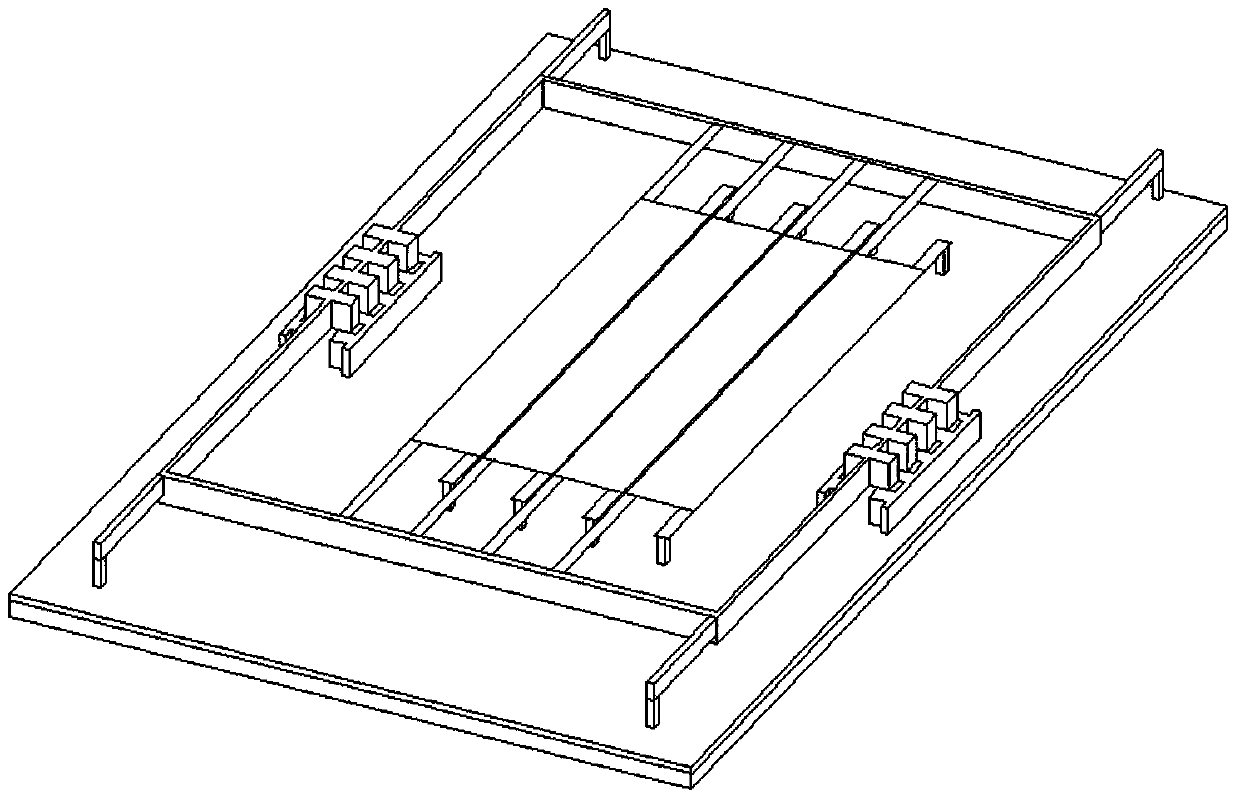
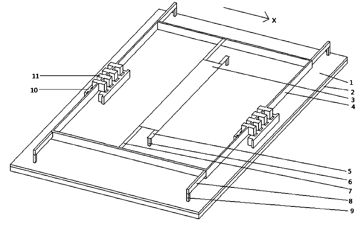
[0025] see figure 1 In this embodiment, the silicon substrate 1 of the louver type MEMS large rotation angle adjustable blazed grating optical modulator and the insulating layer 2 arranged on the silicon substrate 1, the grating mirror surface 3 is supported on the insulating layer by an elastic cantilever beam and a movable frame 4. Above the layer 2, one side of the grating is fixed on the substrate surface through the support beam 5 and two pillars 6, and the other side is connected with the movable frame 4 through the deformation beam 7. The movable frame 4 is fixed on the surface of the substrate 1 by flexible support beams 8 and pillars 9 . The fixed teeth 10 and the movable teeth 11 form a comb drive, and there are two groups. The fixed teeth 10 are fixed on the surface of the substrate 1 , and the movable teeth 11 and the movable frame 4 are integrated. The fixed teeth 10 and t...


PUM


Abstract

The invention relates to the technical field of MEMS light modulators, in particular to an MEMS blazed grating light modulator and an array. The shutter type MEMS large-rotation-corner adjustable blazed grating light modulator comprises a silicon substrate, an insulating layer, a movable frame, flexible beams, a grating mirror plane, double-layer comb tooth drive structures, an elastic cantilever beam, a bias voltage exerting device and a plurality of columns, wherein the insulating layer, the movable frame, the flexible beams, the grating mirror plane, the double-layer comb tooth drive structures, the elastic cantilever beam, the bias voltage exerting device and the columns are arranged on the silicon substrate. One side of the grating mirror plane is fixed to the surface of the substrate through supporting beams and two of the columns, and the other side of the grating mirror plane is connected with the movable frame through a deformation beam and driven by the double-layer comb tooth drive structures. The bias voltage exerting device can exert drive voltages at different levels and different frequencies between movable teeth and fixed teeth, and therefore the movable teeth can deflect and move to drive the movable frame, and the movable frame pulls the grating mirror plane to defect through the deformation beam. Due to the structure, an MEMS blazed grating has the advantages of being large in rotation angle, adjustable in continuous analog, good in controllable capacity, high in diffraction efficiency, high in tuning efficiency and capable of preventing adhesion failure.

Description

technical field [0001] The invention relates to the technical field of MEMS light modulators, in particular to a MEMS blazed grating light modulator and an array. Background technique [0002] Gratings, also known as diffraction gratings, use the principle of multi-slit diffraction to disperse light. It is an important diffraction element widely used in optical systems and the core device of spectral analysis equipment. It is a flat glass or metal sheet engraved with many, many parallel equal-width and equidistant slits, and the grating slits are generally tens to thousands per millimeter. When monochromatic parallel light passes through the grating, it will form a pattern with wider dark stripes and thinner bright stripes, called spectral lines. The position of the spectral lines depends on the wavelength. After the polychromatic parallel light passes through the grating, spectral lines with different wavelengths appear at different positions to form a spectrum. The spect...

Claims


Application Information

Patent Timeline
IPC IPC(8): G02B26/08B81B3/00
Inventor 张智海路远张文凯高玲肖
Owner CHONGQING UNIV
Why Eureka
Try Eureka