
Self-reflection calibration method for space remote sensor on orbit infrared focal plane

A space remote sensor, self-reflection calibration technology, used in TV, color TV parts, electrical components, etc., can solve the problems of opto-mechanical structure deformation, many constraints, limited application scope, etc., to achieve temperature stability and Good uniformity, improved imaging quality, and small deformation of optomechanical structure

Active Publication Date: 2015-07-08
BEIJING RES INST OF SPATIAL MECHANICAL & ELECTRICAL TECH
View PDF2 Cites 2 Cited by
  • Summary
  • Abstract
  • Description
  • Claims
  • Application Information

AI Technical Summary

Problems solved by technology

However, there are certain defects in the calibration of deep cold space: there are many constraints, limited by the satellite platform, camera installation method, working mode, etc., the satellite platform is required to provide a cold space interface for the space remote sensor load in the installation method, and on-orbit calibration When the mode works, the space remote sensor needs to point to the cold space
At the same time, because the space remote sensor needs to reserve a cold space interface, it cannot form a relatively sealed temperature control system, which affects the control of the temperature stability and uniformity of the system, which in turn leads to the deformation of the optical-mechanical structure and affects the imaging quality, thus severely limiting its application range.

Method used

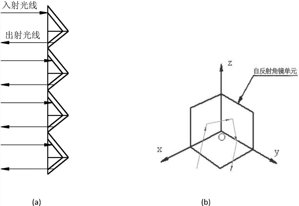
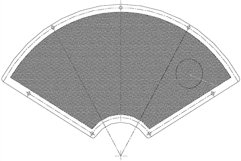

Image

  • Self-reflection calibration method for space remote sensor on orbit infrared focal plane
  • Self-reflection calibration method for space remote sensor on orbit infrared focal plane
  • Self-reflection calibration method for space remote sensor on orbit infrared focal plane

Examples


Embodiment Construction

[0030] Specific embodiments of the present invention will be further described in detail below in conjunction with the accompanying drawings.

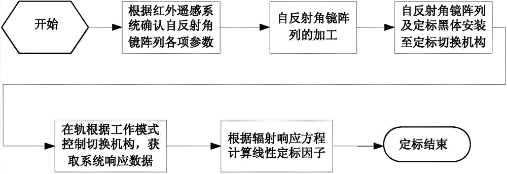
[0031] The space infrared remote sensor referred to in the present invention adopts the combination of refrigerator and radiation refrigeration to refrigerate the detector focal plane assembly, and the refrigeration temperature is 60K~80K, which becomes the cold focal plane; for the secondary imaging off-axis optical system, the calibration The switching mechanism is placed at the position of the primary image plane, and the working mode is switched through the control circuit when it is in orbit, so as to realize the radiation calibration of the imaging system, remove the influence of dark current noise and the background radiation of the local optical path, and realize the process as shown in the attached figure 1 As shown, the steps are as follows:

[0032] (1) Determine the parameters of the self-reflecting cube array according to ...


PUM


Abstract

The invention discloses a self-reflection calibration method for a space remote sensor on the orbit infrared focal plane. Firstly, various parameters of a self-reflection angle mirror array are determined according to a space remote sensor optical system and processing of the self-reflection angle mirror array is completed; then, a black body and the self-reflection angle mirror array are arranged on a calibration switching mechanism, and the space remote sensor is switched among three working modes by using the calibration switching mechanism, and thus radiation response data and the input and output data are obtained; finally, the obtained data are taken into the radiation response equation, and linear calibration factors of the system are calculated to finish calibration. By virtue of calibration on the orbit infrared focal plane, the cold focal plane self-reflection is realized, thereby serving as a high stability calibration source, a reflector does not need to be introduced into a cold space, the influence of noise, such as dark current, of the detector can be eliminated, and reliability and precision of on-orbit detection data of a space remote sensing spectrometer are guaranteed.

Description

technical field [0001] The invention relates to a self-reflection calibration method of the infrared focal plane of a space remote sensor, which is mainly used in the field of multi-spectral imaging and quantitative application of infrared remote sensors, and is especially suitable for remote sensors that cannot use cold space to achieve detector on-orbit radiation calibration. Target situation. Background technique [0002] The thermal infrared detection channel of the aerospace remote sensor, in addition to being used for infrared imaging of ground targets, also has the ability to invert a variety of quantitative ground target feature objects from image data. The key link to realize the quantitative processing is to carry out the radiation calibration of the space remote sensor, that is, to convert the output of the remote sensor to the absolute radiation. The radiation from the on-orbit calibration radiation source is accepted, so as to establish the relationship between...

Claims


Application Information

Patent Timeline
Patent Type & Authority Patents(China)
IPC IPC(8): H04N17/00H04N5/33
Inventor 张丽莎唐绍凡白绍竣刘剑锋赵鑫晋利兵
Owner BEIJING RES INST OF SPATIAL MECHANICAL & ELECTRICAL TECH
Learn More