
chain drive

A technology of chain transmission and chain, which is applied in the direction of transmission device, transmission chain, belt/chain/gear, etc. It can solve the problems of increased power loss, increased friction of guide block, unstable chain, etc., and achieves the effect of reducing sliding resistance

Inactive Publication Date: 2016-05-25
TSUBAKIMOTO CHAIN CO
View PDF6 Cites 0 Cited by
  • Summary
  • Abstract
  • Description
  • Claims
  • Application Information

AI Technical Summary

Problems solved by technology

At this time, among the guides, if the guide shoe on which the moving surface of the chain sliding contact is formed is made of synthetic resin, the guide shoe may soften due to the temperature rise caused by frictional heat.
Moreover, when the guide block softens, since the sliding resistance acting on the chain becomes larger, the friction loss on the chain increases, the power loss of the power source (such as an engine) used to drive the chain transmission increases, and there is an increase in the energy consumption rate. problem, and there is a problem that the wear of the guide block increases and the durability of the two guides decreases
[0011] And, at the entry-side end and the exit-side end of each guide, since the motion state of the chain is unstable compared with the central portion of each guide, the chain tends to be unstable, and the instability caused by this error occurs. steady noise
And, when only one side of the inner link and the outer link of the chain is always in sliding contact with the entering side end and the leaving side end, there is a periodic noise peculiar to the inner link or the outer link (hereinafter referred to as "Periodic noise") becomes larger

Method used


Image

  • chain drive
  • chain drive
  • chain drive

Examples


Embodiment

[0045] Below, refer to Figure 1 to Figure 8 Examples of the present invention will be described.

[0046] Figure 1 ~ Figure 4 It is a figure for explaining the 1st Example of this invention.

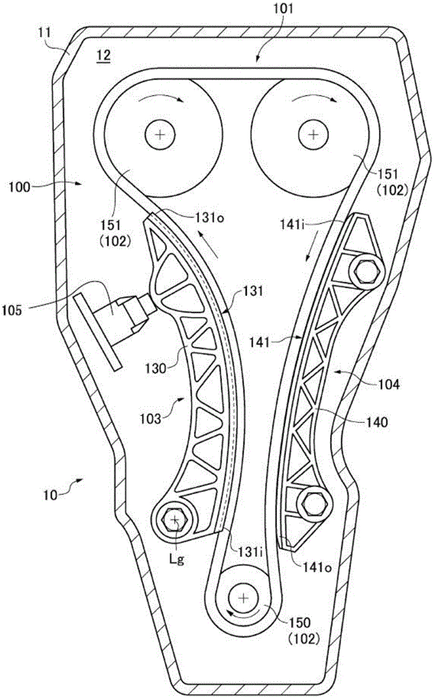
[0047] when referring to figure 1 In the first embodiment, the chain transmission device 100 is included in the motor vehicle engine 10 as a machine. Furthermore, the chain transmission 100 is a timing chain transmission for driving a valve train of the engine 10 .

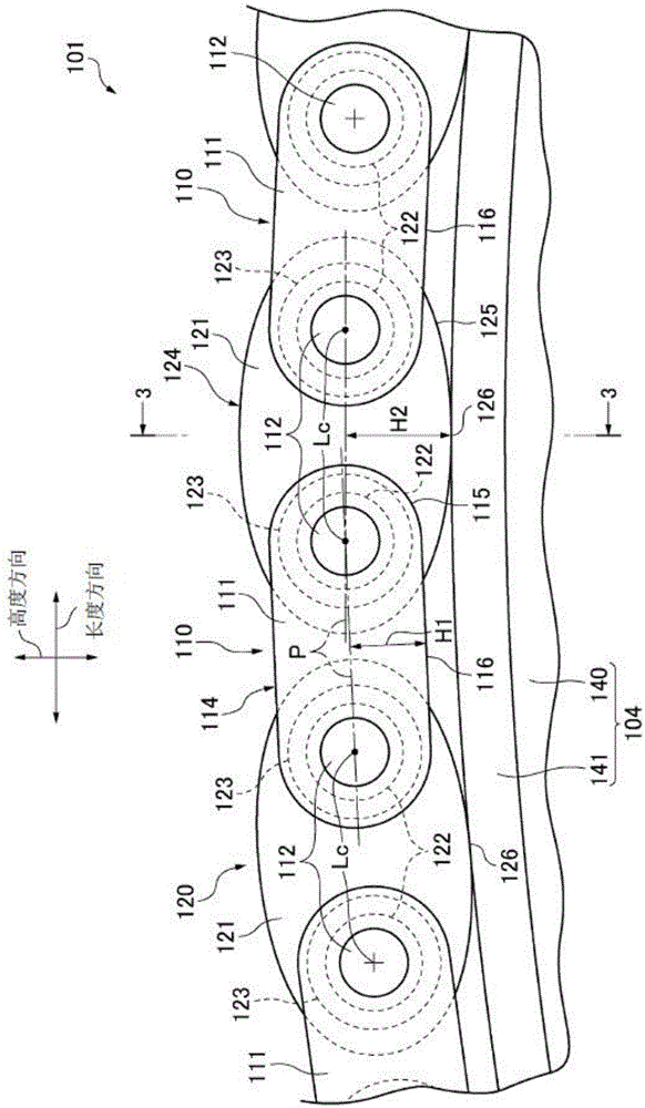
[0048] The chain transmission device 100 has: a chain 101, which is a roller chain; a sprocket group 102, which is formed by a plurality of sprockets 150, 151 passed by the chain 101; a movable guide 103, a fixed guide 104, which are in sliding contact The chain 101 in the moving state is used to guide the moving chain 101 driven by the sprocket group 102 ; and the tensioning device 105 is used to apply tension to the chain 101 through the movable guide 103 .

[0049] The chain transmission device 100 is arranged in t...


PUM


Abstract

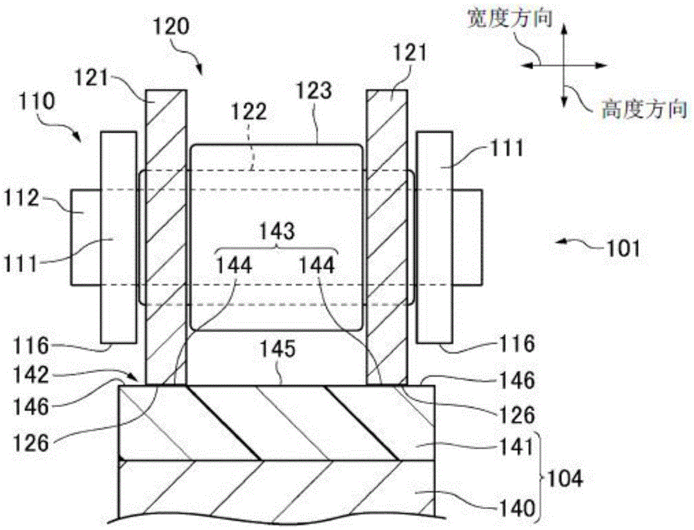
The invention provides a chain transmission device. That a resin guide block is softened due to friction heat generated when an outer connecting piece and an inner connecting piece of a chain are in slide contact is prevented, and frictional loss and energy consumption are reduced, at the same time, the durability of the resin guide block is improved, and noise generated when the chain enters and breaks away from a chain guiding member is reduced. Specifically, the chain (101) is in slide contact with a movable guiding block (131) at a chain loose side, and the chain is in slide contact with a fixed guiding block (141) at a tensioning side. A motion face of at least one of the movable guiding block (131) and the fixed guiding block (141) is made of a synthetic resin. The outer connecting piece (110) of the chain (101) is only in slide contact with the motion face (133) of the movable guiding block or the motion face (143) of the fixed guiding block, and the inner connecting piece (120) is only in slide contact with the other motion face.

Description

technical field [0001] The invention relates to a chain transmission device, which is provided with a movable guide piece and a fixed guide piece which are in sliding contact with the chain passing over the sprocket group. The chain transmission is, for example, a timing chain transmission provided in an automobile engine. Background technique [0002] The existing chain transmission device has: a chain, which is flexibly connected with an outer connecting piece and an inner connecting piece adjacent in the length direction; a sprocket group, which is passed by the chain; The chain is in sliding contact; and the fixed guide is in sliding contact with the chain on the tensioned side of the chain. [0003] Moreover, a chain transmission device in which only the inner link of the chain is in sliding contact with the movable guide and the fixed guide is known (for example, refer to Patent Document 1), and only one of the inner link and the outer link of the chain is also known....

Claims


Application Information

Patent Timeline
Patent Type & Authority Patents(China)
IPC IPC(8): F16H7/06F16H7/18F16G13/06
CPCF16G13/06F16H7/06F16H7/18F16H2007/185
Inventor 近能雅彦佐佐木健雄
Owner TSUBAKIMOTO CHAIN CO
Learn More