Plane mirror reflection based micro-cantilever deflection detecting system of micro-cantilever array sensor and detecting method
An array sensor and micro-cantilever technology, applied in the direction of using optical devices to transmit sensing components, can solve the problems of particle motion, detection data errors, and inability to guarantee the consistency of laser beams, to avoid interference, easy to build, and to ensure consistency sexual effect
- Summary
- Abstract
- Description
- Claims
- Application Information
AI Technical Summary
Problems solved by technology
Method used
Image

Examples
Embodiment 1
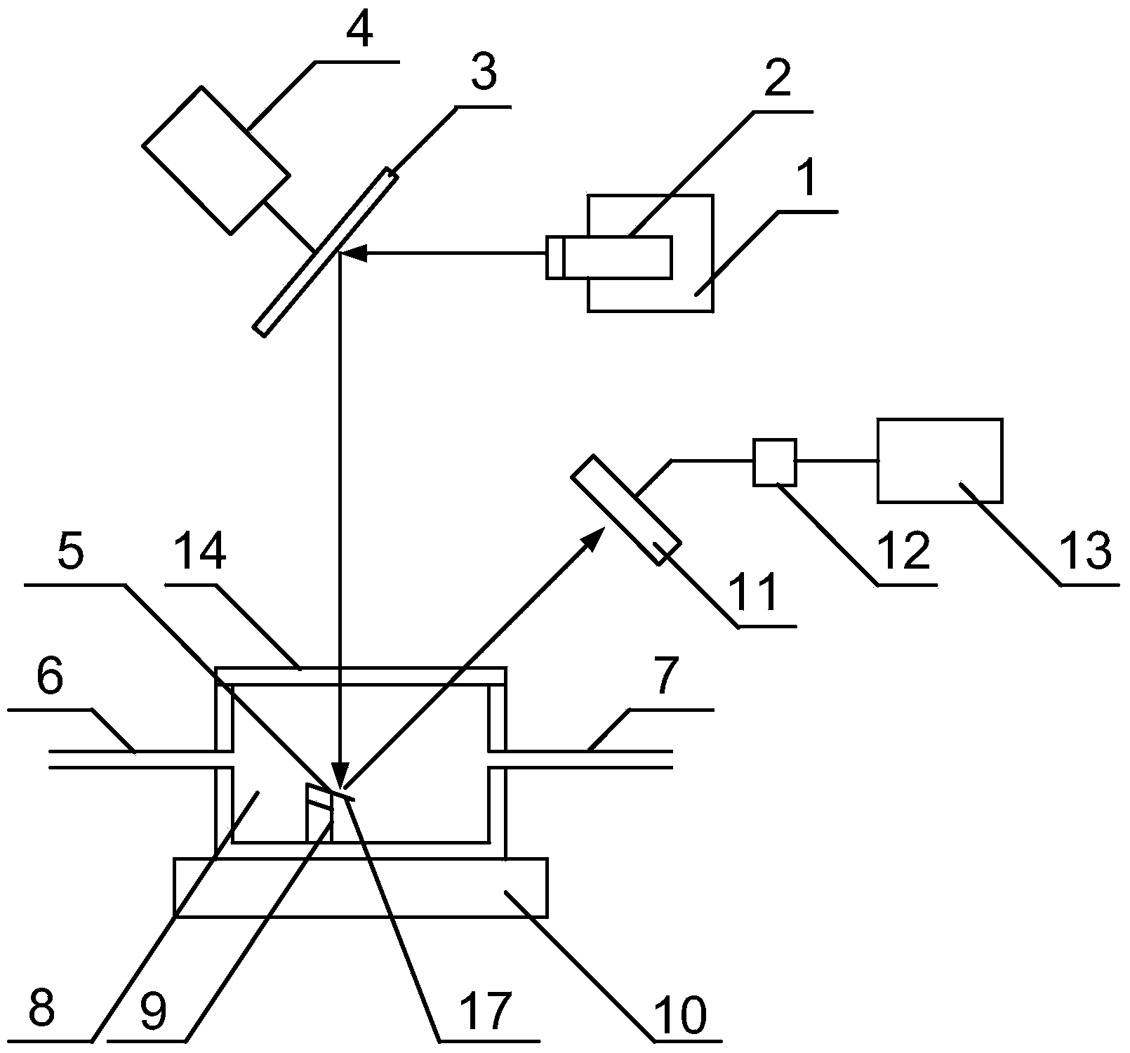
[0050] Such as figure 1 As shown, the detection system includes:
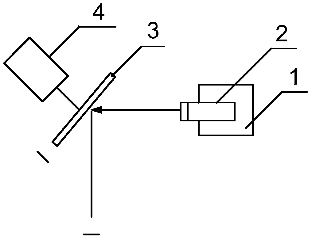
[0051] A laser 2 for emitting horizontal laser beams; the laser is fixed on the movable displacement platform 1, and the micro-displacement platform can be displaced in the horizontal and vertical directions; the laser is a semiconductor laser, and the laser light source is a monochromatic laser within the range of 632nm-780nm light source.
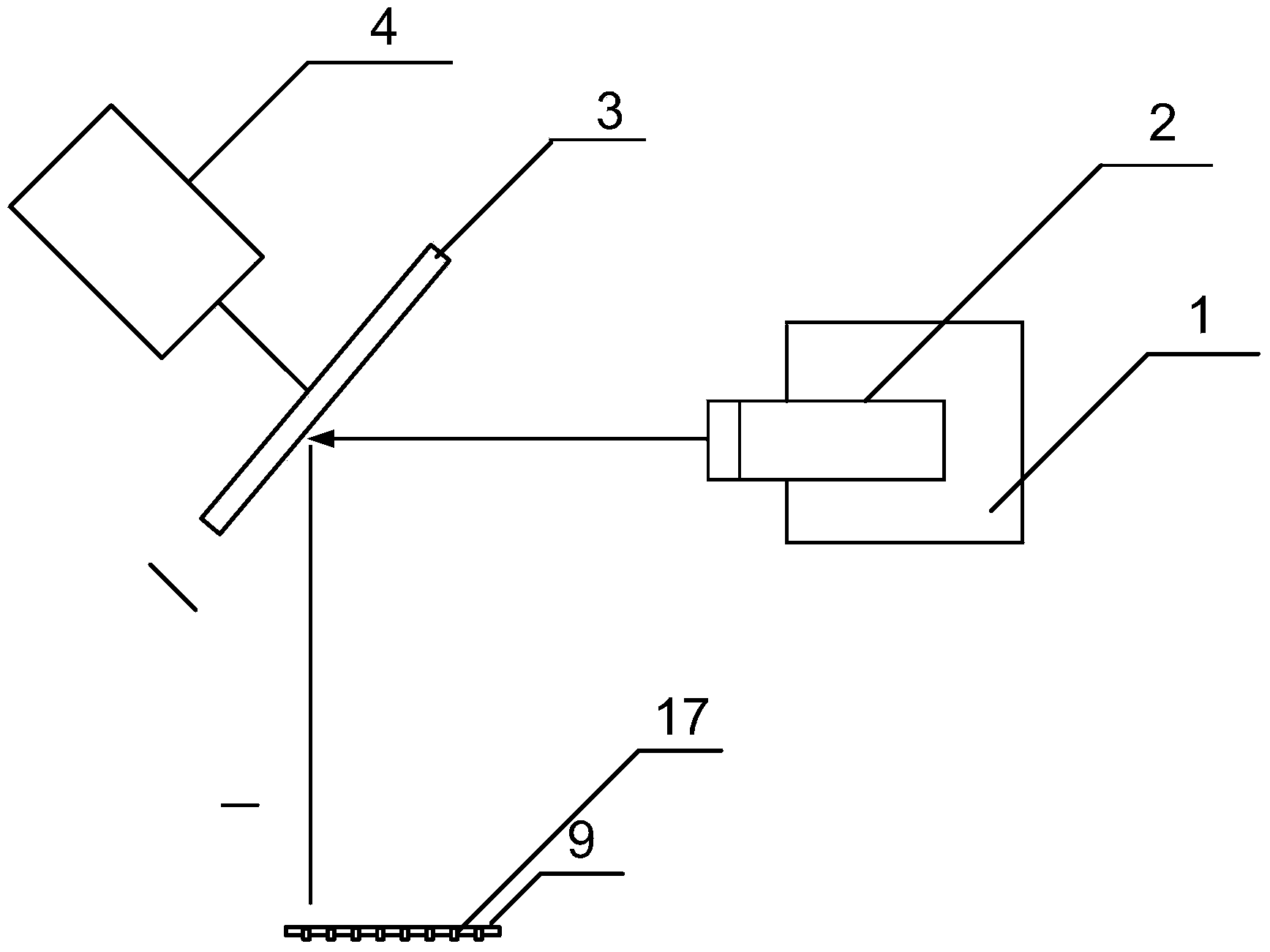
[0052] A plane mirror 3, the plane mirror is obliquely arranged in front of the horizontal laser beam, and the horizontal laser beam is reflected into a reflected laser beam directed to the micro-cantilever beam array 5, and the reflected laser beam is used for the free end of the micro-cantilever beam 17 of the micro-cantilever beam array to be measured Scanning; the plane mirror is fixed on the voice coil motor 4, and the voice coil motor is used to make the plane mirror reciprocate horizontally; or it is fixed on the motor shaft 16 of the stepper motor 15, and the step...
Embodiment 2
[0058] Embodiment 2 Micro-cantilever deflection detection method of micro-cantilever array sensor based on plane mirror translation
[0059] The method comprises the steps of:
[0060] 1) Place the micro-cantilever array to be tested on the substrate holding platform in the solvent pool, so that the micro-cantilever array is arranged in an oblique direction. The solvent pool is airtight, with a transparent glass window on the top, and the solvent pool passes through the inlet pipe and The outlet pipe controls the entry and exit of solvent;
[0061] 2) Adjust the initial position of the laser through the movable displacement platform, and adjust the initial position of the plane mirror at the same time, so that the horizontal laser beam emitted by the laser is reflected by the plane mirror and projected vertically to the free end of the micro-cantilever beam of the micro-cantilever beam array through the glass window; Such as figure 1 shown.
[0062] 3) Use the voice coil mo...
Embodiment 3
[0064] Embodiment 3 Micro-cantilever deflection detection method based on the micro-cantilever array sensor rotating by plane mirror
[0065] The method comprises the steps of:
[0066] 1) Place the micro-cantilever array to be tested on the substrate holding platform in the solvent pool, so that the micro-cantilever array is arranged in an oblique direction. The solvent pool is airtight, with a transparent glass window on the top, and the solvent pool passes through the inlet pipe and The outlet pipe controls the entry and exit of solvent;
[0067] 2) Adjust the initial position of the laser through the movable displacement platform, and adjust the initial position of the plane mirror at the same time, so that the horizontal laser beam emitted by the laser is reflected by the plane mirror and projected vertically to the free end of the micro-cantilever beam in the middle of the micro-cantilever beam array through the glass window ;
[0068] 3) Use the stepping motor to driv...
PUM
 Abstract
Description
Claims
Application Information
 - Generate Ideas
- Intellectual Property
- Life Sciences
- Materials
- Tech Scout
- Unparalleled Data Quality
- Higher Quality Content
- 60% Fewer Hallucinations
Browse by: Latest US Patents, China's latest patents, Technical Efficacy Thesaurus, Application Domain, Technology Topic, Popular Technical Reports.
© 2025 PatSnap. All rights reserved.Legal|Privacy policy|Modern Slavery Act Transparency Statement|Sitemap|About US| Contact US: help@patsnap.com