
LED lamp

A technology of LED lamps and LED lamp beads, which is applied in the direction of lamp shades, cooling/heating devices of lighting devices, lighting and heating equipment, etc. It can solve the problems of long start-up time, fragile products, high power consumption, etc., and expand the lighting area , Large lighting angle, flexible effects

Active Publication Date: 2014-05-28
RED100 LIGHTING CO LTD
View PDF5 Cites 12 Cited by
  • Summary
  • Abstract
  • Description
  • Claims
  • Application Information

AI Technical Summary

Problems solved by technology

[0003]On the one hand, with the development of LED technology, LED has been more and more widely used in the field of lighting, so its heat dissipation problem has also received more and more attention , especially in high-power LED lamps, high-power LEDs have a large rated operating current, and most of their output power is converted into conduction heat. Will affect the luminous efficiency and life of LED lamps
In addition, because the LED light source is limited by its light-emitting surface, its light-emitting angle is limited
However, in the existing technology, LED lamps have many defects such as bulky and single heat dissipation structure, poor applicability of lamps, single light-emitting surface, and poor integrated IP dustproof and waterproof grades.
In addition, the maintenance and disassembly of the existing indoor and outdoor high-power LED product solutions are inconvenient, and the replacement cost is high
[0004]On the other hand, high-pressure mercury vapor lamps are widely used due to their advantages of wide luminous surface and beautiful appearance. High consumption, the principle of discharge luminescence leads to its mercury content, which is not environmentally friendly, long start-up time and intermittent start-up time, and the product is fragile during transportation and use

Method used


Image

  • LED lamp
  • LED lamp
  • LED lamp

Examples


Embodiment Construction

[0022] The preferred embodiments of the present invention will be described in detail below in conjunction with the accompanying drawings, so that the advantages and features of the present invention can be more easily understood by those skilled in the art, so as to define the protection scope of the present invention more clearly.

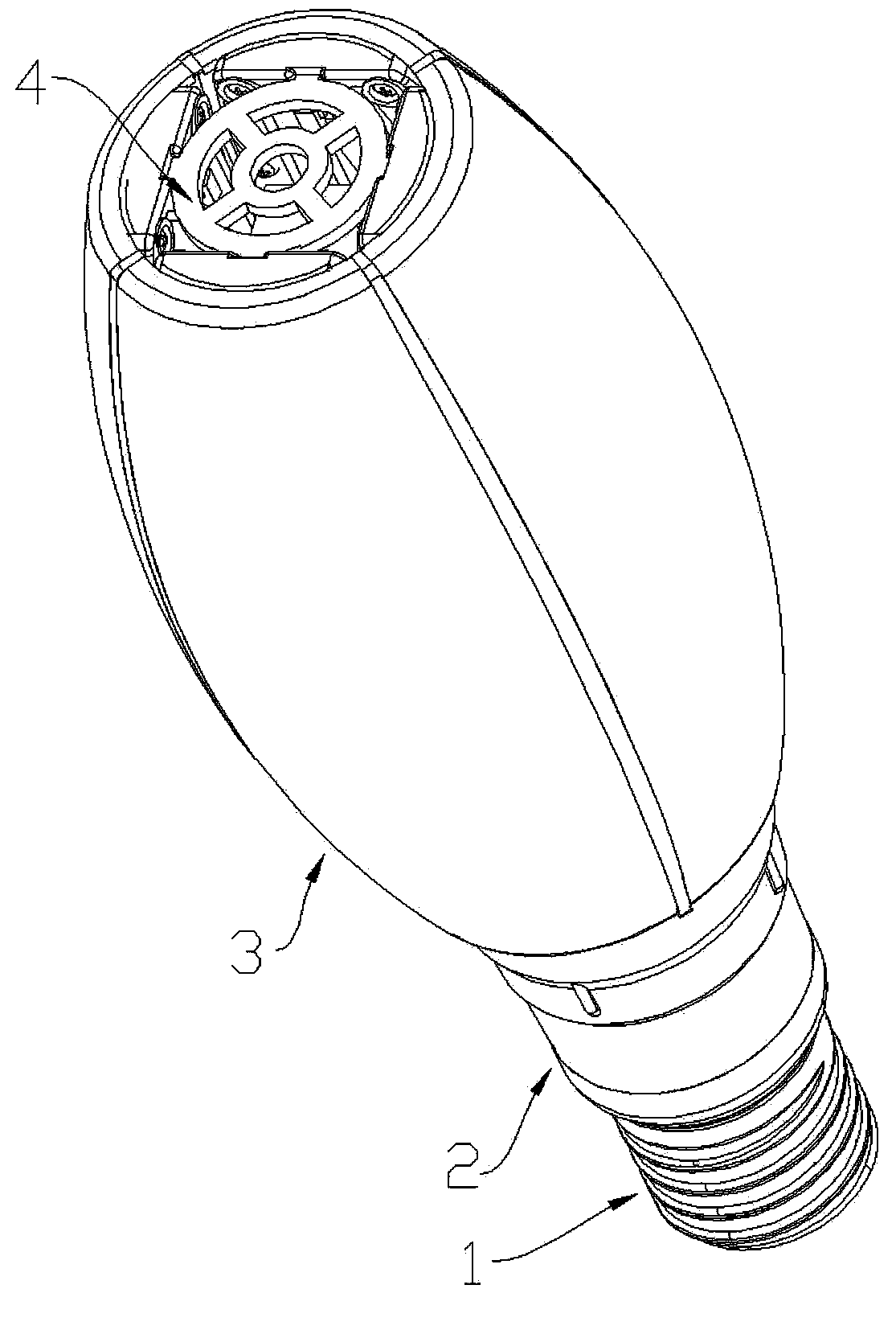
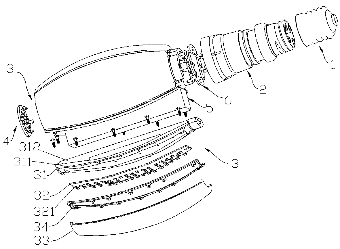
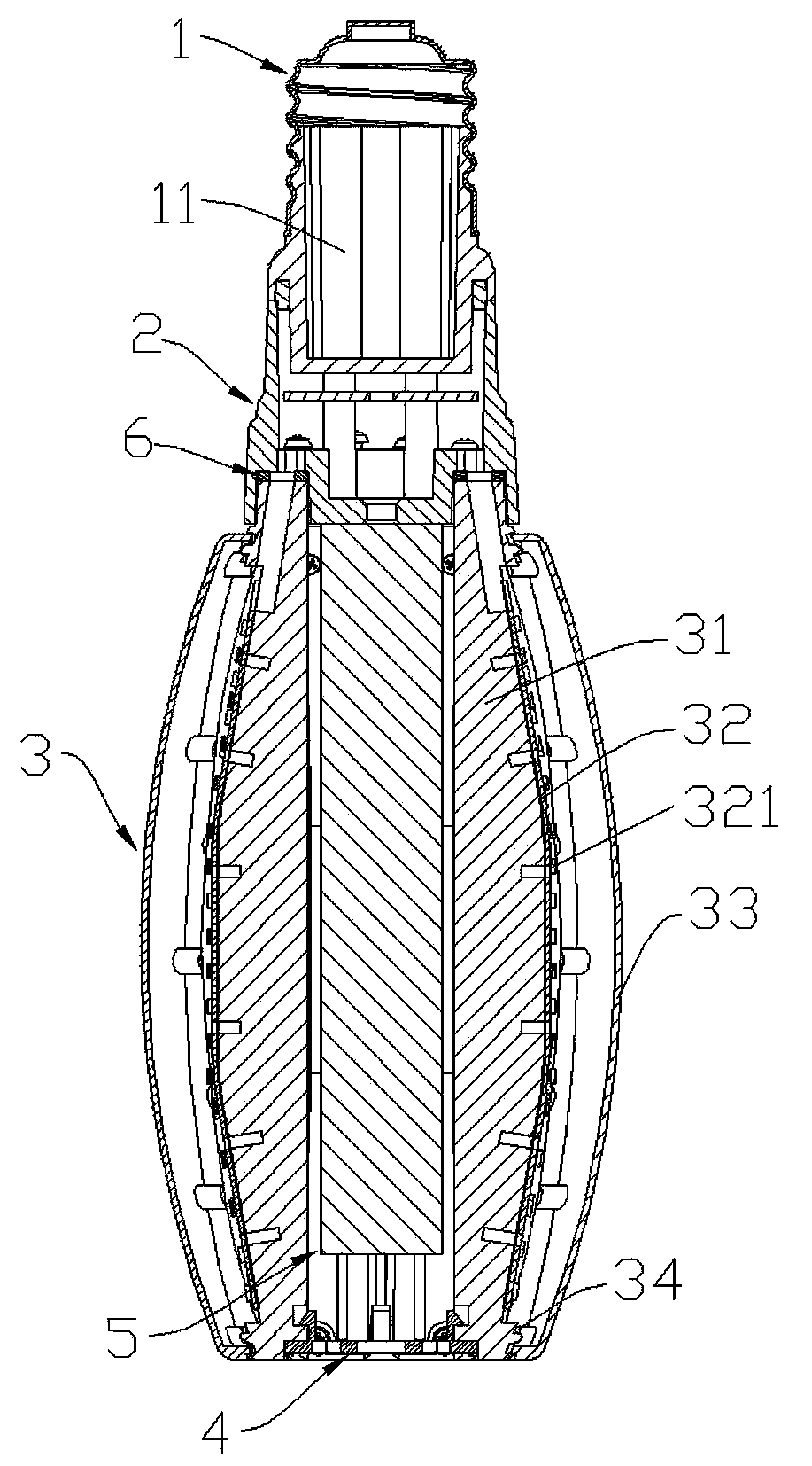
[0023] combine figure 1 As shown, an LED lamp includes a lamp base 1 , a heat sink 2 arranged on one end of the lamp base 1 rotatably around the central axis of the lamp base 1 , and four light emitting units 3 . The other end of the lamp holder 1 is used for electrically connecting with an external power source and fixing and installing the LED lamp in the use area. Four light emitting units 3 are fixedly installed on the same side of the heat sink 2 by screws, and the heat sink 2 is screwed to the lamp cap 1 so that the light emitting unit 3 can rotate 1360 degrees relative to the lamp cap to change the irradiation angle of the light emitt...


PUM


Abstract

The invention discloses an LED lamp which comprises a lamp holder, a heat dissipation base which is arranged at one end of the lamp holder in the mode that the heat dissipation base can rotate around the axis of the lamp holder, and one or more light-emitting units. The other end of the lamp holder is used for being connected with an external power supply. Each light-emitting unit comprises a heat dissipation device arranged on the heat dissipation base, a lamp panel which is attached to the heat dissipation device, a plurality of LED lamp beads which are fixedly arranged on the lamp panel and integrally packaged, and a lampshade which is connected with the heat dissipation device and covers the LED lamp beads. The LED lamp beads are electrically connected with the external power supply. According to the LED lamp, the light-emitting angle can be adjusted.

Description

technical field [0001] The invention relates to an LED lamp, in particular to a high-power LED energy-saving lamp imitating a high-pressure mercury vapor lamp. Background technique [0002] LED (Light Emitting Diode, light-emitting diode) energy-saving lighting will gradually replace traditional lighting sources has become a consensus in the industry, and LED lighting technology is developing towards maturity, low cost and popularization. [0003] On the one hand, with the development of LED technology, LED has been more and more widely used in the field of lighting, so its heat dissipation problem has also received more and more attention, especially in high-power LED lamps, high-power LEDs have large rated The working current, most of its output power is converted into conduction heat. If no heat dissipation measures are taken, the accumulated heat will cause the temperature of the LED chip to be too high, which will affect the luminous efficiency and life of the LED lamp....

Claims


Application Information

Patent Timeline
Patent Type & Authority Applications(China)
IPC IPC(8): F21V14/02F21V21/30F21V3/02F21V29/00F21V31/00F21Y101/02F21V29/70F21V29/76F21Y115/10
Inventor 林利民
Owner RED100 LIGHTING CO LTD
Learn More