
Oil melting point measurer

A melting point determination and grease technology, which is applied in the investigation phase/state change and other directions, can solve the problems of cumbersome operation, poor measurement accuracy and stability, and difficulty in accurately recording the melting point value, and achieves accurate melting point determination, long service life, and automation. high degree of effect

Inactive Publication Date: 2014-05-14
ZHANGJIAGANG EENTRY EXIT INSPECTION & QUARANTINE BUREAU
View PDF7 Cites 0 Cited by
  • Summary
  • Abstract
  • Description
  • Claims
  • Application Information

AI Technical Summary

Problems solved by technology

However, if the manual test method is used to measure according to the standard, not only the operation is cumbersome, but also it is difficult to accurately record the melting point value, and the measurement accuracy and stability are poor.

Method used


Image

  • Oil melting point measurer
  • Oil melting point measurer
  • Oil melting point measurer

Examples


Embodiment Construction

[0023] Specific embodiments of the present invention will be described in detail below in conjunction with the accompanying drawings.

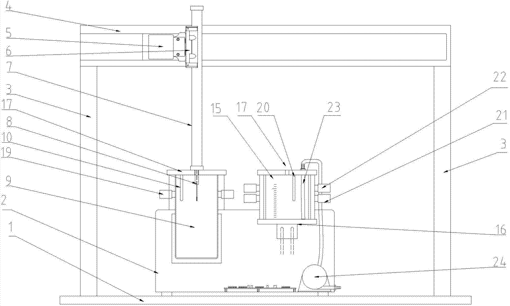
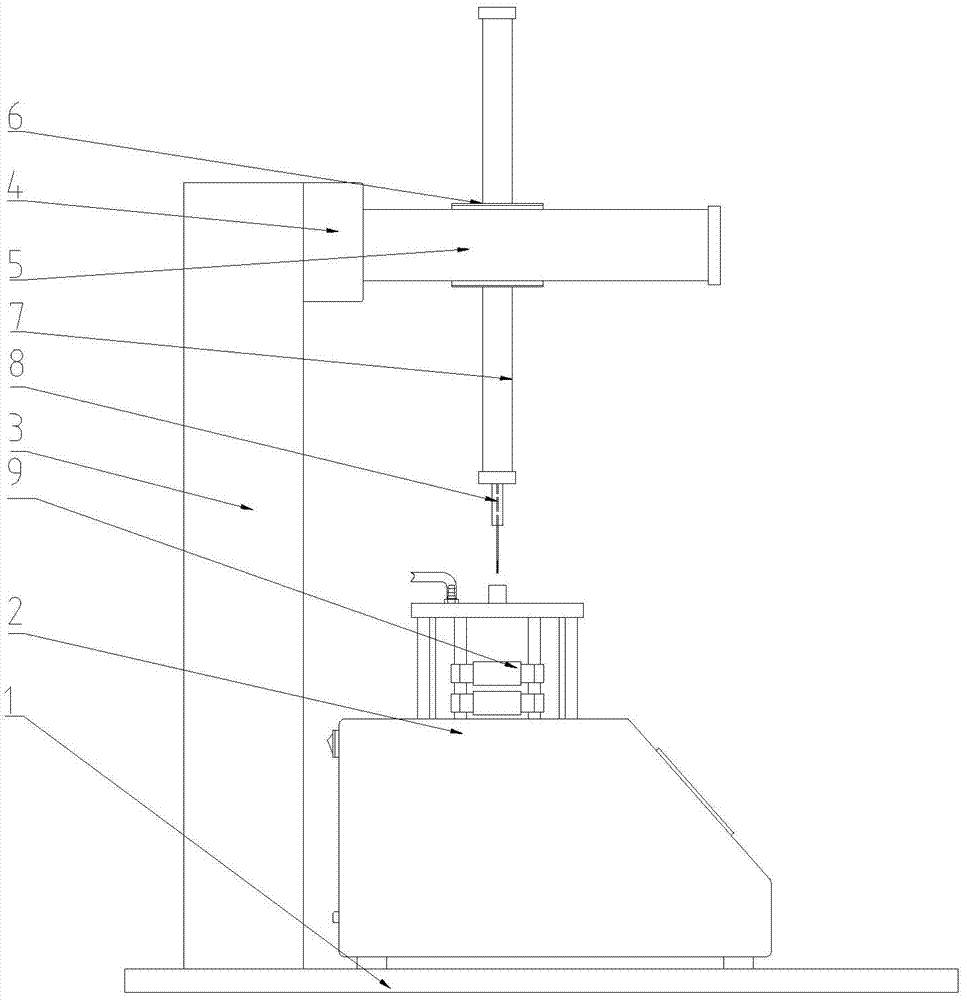
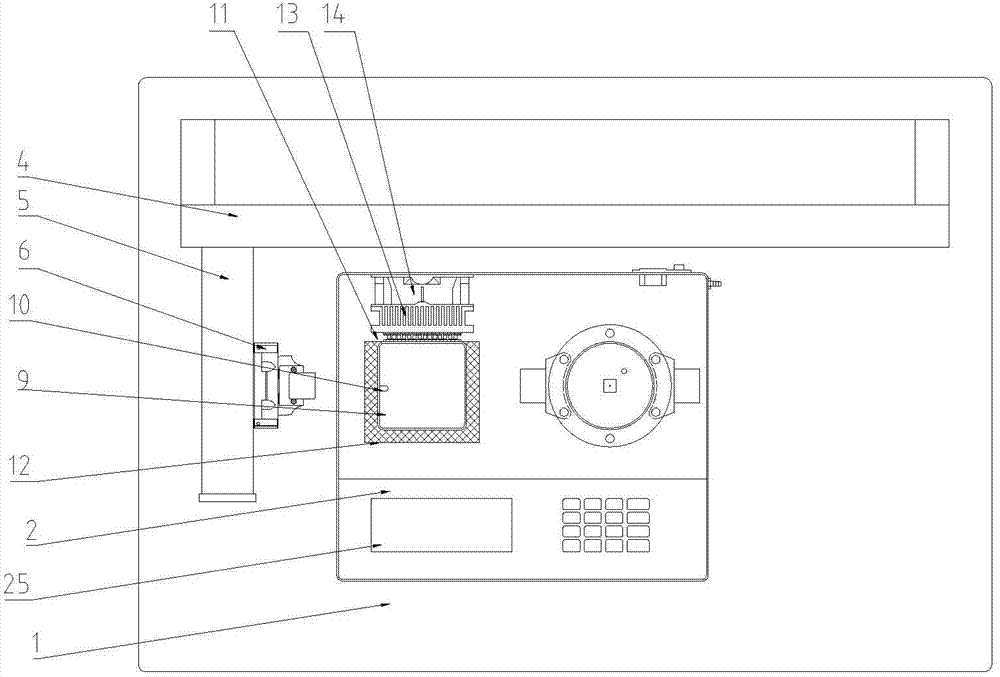
[0024] like Figure 1-3 As shown, a grease melting point tester includes a base 1, a measuring base 2 is arranged on the base 1, a PLC (not shown in the figure) is arranged in the measuring base 2, and a Connected display 25 . The base 1 is provided with two uprights 3 side by side, the uprights 3 are provided with an upper bracket 4, and the upper bracket 4 is provided with an upper slider 5 and a first driving device controlled by PLC to drive the upper slider 5 to slide. The first drive device includes a first drive motor (not shown in the figure) arranged on the upper slider 5, a drive gear (not shown in the figure) is arranged on the output shaft of the first drive motor, and a drive gear (not shown in the figure) is arranged on the upper bracket 4 A rack (not shown) matched with the drive gear is provided; the side of the upper slider ...


PUM


Abstract

The invention discloses an oil melting point measurer which can achieve a high-accuracy detection result. The oil melting point measurer comprises a base, wherein a measurement substrate is arranged on the base; a PLC (programmable logic controller) is arranged in the measurement substrate; a display connected with the PLC is arranged on the measurement substrate; a sample clamping arm controlled by the PLC to move is arranged on the base; a refrigeration tank and a refrigeration module controlled by the PLC are arranged on the measurement substrate; a first temperature sensor is arranged in the refrigeration tank; a heating tank is arranged on the measurement substrate; a heating device controlled by the PLC and an air turbulent flow pipeline connected with an air compressor which is controlled by the PLC are arranged on the heating tank measurement substrate; a refrigeration timing device connected with the PLC is arranged on the measurement substrate; a second temperature sensor connected with the PLC is arranged in the heating tank; a first infrared detector which is connected with the PLC and is used for detecting whether a sample is inserted in place is arranged in the heating tank; an infrared sensor which is connected with the PLC and is used for detecting the infrared transmittance of the oil column is arranged on the measurement substrate at the position corresponding to a sample oil column.

Description

technical field [0001] The invention relates to an instrument for measuring the melting point of oil. Background technique [0002] The detection of the melting point of fats and oils should adopt the method specified in GB / T24892-2010 / ISO 6321:2002: under the specified conditions, prepare a solidified fat column at one end of the capillary, immerse it in a water bath of a certain depth, press the The temperature at which the fat column slides upward at a predetermined rate of temperature rise is recorded as the melting point of the fat. However, if the method of manual testing is used to measure according to the standard, not only the operation is cumbersome, but also it is difficult to accurately record the melting point value, and the measurement accuracy and stability are poor. Contents of the invention [0003] The technical problem to be solved by the present invention is to provide an instrument for measuring the melting point of fats and oils with high accuracy of...

Claims


Application Information

Patent Timeline
Patent Type & Authority Applications(China)
IPC IPC(8): G01N25/04
Inventor 张慧刘一军王玥顾强夏拥军卢志琴
Owner ZHANGJIAGANG EENTRY EXIT INSPECTION & QUARANTINE BUREAU
Learn More