
Belt-broken protective device with deceleration function

A protection device and belt-breaking technology, which is applied to the conveyor control device, transportation and packaging, conveyor objects, etc., can solve the problems of the impact of the conveyor fuselage frame, damage to the fuselage frame parts, etc., and achieve low production costs. , the effect of prolonging the service life and reducing the impact damage

Active Publication Date: 2014-05-14
SHANDONG KEDA ELECTROMECHANICAL TECH CO LTD
View PDF9 Cites 4 Cited by
  • Summary
  • Abstract
  • Description
  • Claims
  • Application Information

AI Technical Summary

Problems solved by technology

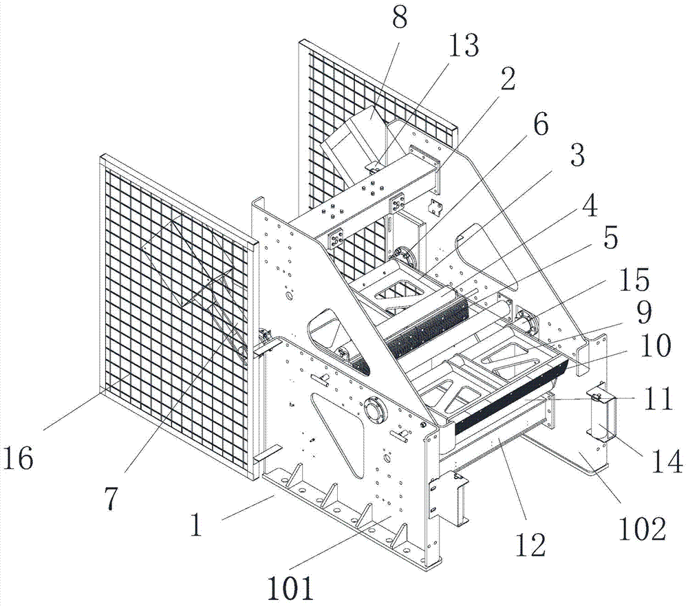
The broken belt catcher is used as a supporting roller under normal conditions. When a broken belt occurs, the tension of the conveyor belt drops suddenly, and the upper and lower belt catchers are triggered by the gravity of the parts to catch the broken belt. Although the belt catcher can catch the upper and lower tapes at the same time after the broken belt, but because of the fast catch, it is easy to cause a great impact on the conveyor fuselage during the catch process, causing the fuselage damage to parts

Method used


Image

  • Belt-broken protective device with deceleration function
  • Belt-broken protective device with deceleration function
  • Belt-broken protective device with deceleration function

Examples


Embodiment approach 1

[0032] Implementation mode one: if Figure 4 and 5As shown, the damping mechanism includes an oil tank 207 arranged on the frame 1 and an oil cylinder 212 arranged between the stationary beam 201 and the movable beam 203. There is a gap at the bottom of the oil cylinder 212. An oil inlet 214 and an oil outlet 215 are arranged on the oil cylinder 212. The oil inlet 214 is located above the oil outlet 215. The oil inlet 214 passes through the oil supply pipeline 211 and the oil outlet of the oil tank 207. 208, the oil outlet 215 is connected to the oil return end 209 of the oil tank 207 through the oil return line 210, the oil return end 209 of the oil tank 207 is provided with a throttle valve, and the oil cylinder 212 is provided with a first piston rod 216, the first piston rod The bottom end of 216 is fixedly connected with the first adjusting disc 217, and the first adjusting disc 217 is provided with an oil seal 218 for plugging the above-mentioned oil inlet 214. The bott...

Embodiment approach 2

[0033] Implementation mode two: if Figure 4 and Figure 6 As shown, the damping structure includes an air pump 219 arranged on the frame 1 and an air cylinder 226 arranged between the stationary beam 201 and the movable beam 203. There is a gap at the bottom end of the cylinder 226. An air inlet 224 and an air outlet 225 are provided on the cylinder 226. The air inlet 224 is located above the air outlet 225. The air inlet 224 is connected to the air outlet 220 of the air pump 219 through an air supply pipeline 221. The air port 225 is connected to the air return end of the air pump 219 through the air return pipeline 223. The air return end of the air pump 219 is provided with a gas speed regulating valve, and the second piston rod 230 is arranged in the cylinder 226, and the bottom end of the second piston rod 230 is fixedly connected There is a second adjustment disc 228, and the second adjustment disc 228 is provided with an air seal 229 for blocking the above-mentioned a...


PUM


Abstract

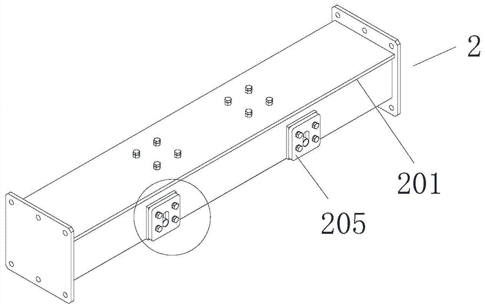
The invention discloses a belt-broken protective device with a deceleration function. The belt-broken protective device comprises a rack and a capturing mechanism. The capturing mechanism comprises an upper conveyor belt capturing part and a lower conveyor belt capturing part. The upper conveyor belt capturing part comprises a movable upper capturing branch part which can swing upwards under the action of the gravity and a static upper capturing branch part arranged on the upper portion of the rack. The movable upper capturing branch part swings towards and near the static upper capturing branch part which is located above the movable upper capturing branch part, and an upper portion clamping gap is formed by the match of the movable upper capturing branch part and the static upper capturing branch part and is capable of capturing an upper conveyor belt. The static upper capturing branch part is an upper portion capturing beam, and the upper portion capturing beam comprises a regulator for buffering and decelerating. The regulator comprises a static beam, a movable beam and a damping structure, wherein the movable beam locates below the static beam and is capable of moving upwards under the action of the upper capturing movable branch part, and the damping structure is used for supplying resistance for the upward movement of the movable beam. The regulator is arranged to supply a deceleration effect on capturing a conveyor belt, so that the impact and damage on the rack during a capturing process are reduced, and the service life of the rack is prolonged.

Description

technical field [0001] The invention relates to a broken belt protection device, in particular to a broken belt protection device with deceleration function. Background technique [0002] Belt conveyors are widely used in many fields such as mining, metallurgy, chemical industry, light industry, coal, ports, etc. With the increase of conveying distance, wear caused by conveyor belt transmission and maintenance errors, belt conveyors will be damaged during operation. In the event of a broken belt accident, in order to avoid huge losses caused by a broken belt accident, a broken belt arresting device is generally installed on the belt conveyor. [0003] Patent CN201713083U discloses a broken belt catcher for a belt conveyor, which includes an upper tape catcher and a lower tape catcher. The upper catch static part fixed on the upper part of the frame, the upper catch dynamic part swings to and approaches the upper catch static part above it, and cooperates with the upper catc...

Claims


Application Information

Patent Timeline
IPC IPC(8): B65G43/06
Inventor 田树涛包继华姜雪杜延旭朱坤海李永浩成祥宁
Owner SHANDONG KEDA ELECTROMECHANICAL TECH CO LTD
Learn More