
A six-channel air particle sampler

A technology of air particulate matter and sampler, applied in the direction of sampling devices, etc., can solve the problems of loss, inconvenient operation, bulky instrument, etc., and achieve the effect of light weight, easy movement, and small volume

Active Publication Date: 2016-03-23
QINGDAO ZHONGRUI INTELLIGENT INSTR
View PDF9 Cites 1 Cited by
  • Summary
  • Abstract
  • Description
  • Claims
  • Application Information

AI Technical Summary

Problems solved by technology

The spacing between multiple sampling heads of this instrument must meet the requirements of HJ656-2013. Each sampling head is connected to the filter membrane through a long connecting rod (ie, a rectifying rod). The head support will cause a certain loss and affect the correctness of the sampling results
In addition, it will cause the defect that the instrument is bulky and inconvenient to operate.

Method used


Image

  • A six-channel air particle sampler
  • A six-channel air particle sampler
  • A six-channel air particle sampler

Examples


Embodiment 1

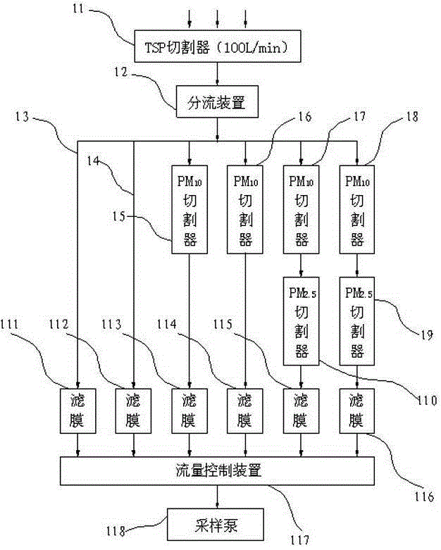
[0027] Such as figure 1 As shown, the sampling pump 118 sucks ambient air containing particulate matter into the TSP cutter 11 at a flow rate of 100 L / min. Under this flow rate, the TSP cutter 11 excludes particulate matter with an aerodynamic particle size greater than 100 μm from the sampler, The particles with an aerodynamic diameter of ≤100 μm enter into the flow splitting device 12 along with the airflow. The flow control device 117 precisely controls the flow rate entering the six air paths to be 16.67L / min, the sampling filter membrane is a standard filter membrane with a diameter of 47mm, and the splitter device 12 ensures that the air flow entering each air path is evenly distributed according to the principle of isotropy. The connecting rod 13 and the connecting rod 14 are directly connected to the filter membrane 111 and the filter membrane 112 , and the particles trapped on the filter membrane 111 and the filter membrane 112 are TSP. The PM10 cutter 15 and the PM1...

Embodiment 2

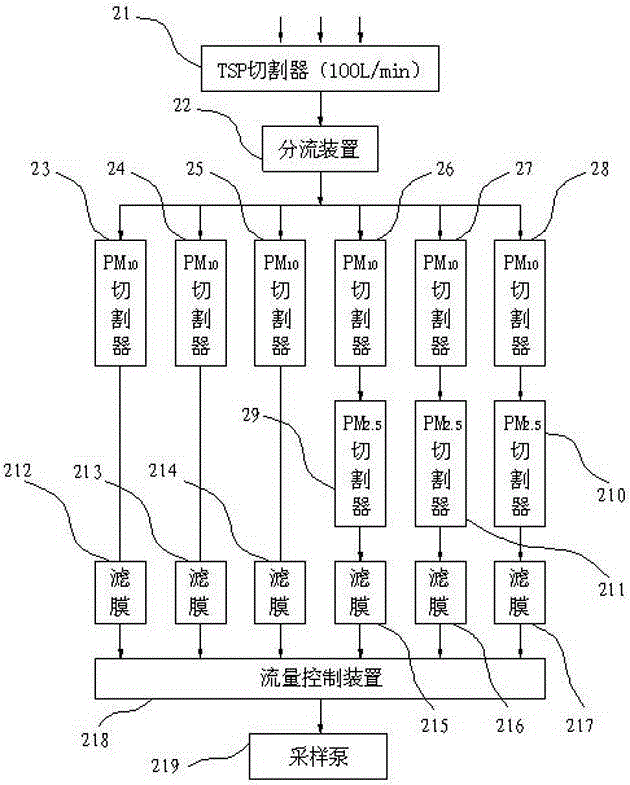
[0034] Such as figure 2 As shown, the sampling pump 219 sucks ambient air containing particulate matter into the TSP cutter 21 at a flow rate of 100 L / min. Under this flow rate, the TSP cutter 21 excludes particulate matter with an aerodynamic particle size greater than 100 μm from the sampler, The particles with an aerodynamic diameter of ≤100 μm enter into the flow splitting device 22 along with the airflow. The flow control device 218 precisely controls the flow rate entering the six air paths to be 16.67L / min, the sampling filter membrane is a standard filter membrane with a diameter of 47mm, and the splitter device 22 ensures that the air flow entering each air path is evenly distributed according to the principle of isotropy. The PM10 cutter 23 , the PM10 cutter 24 and the PM10 cutter 25 are directly connected to the filter membrane 212 , the filter membrane 213 and the filter membrane 214 . The PM10 cutter 23, the PM10 cutter 24 and the PM10 cutter 25 intercept the pa...


PUM

PropertyMeasurementUnit
angleaaaaaaaaaa
diameteraaaaaaaaaa

Abstract

The invention discloses a six-channel air particle sampling device. The sampling device adopts a dividing device to divide collected TSP particles into six parts according to isotropy, six paths of air can be any combination of a straight pipe, PM10 and PM10 cutter to PM2.5 cutter, the obtained particles can be any combination of TSP, PM10 and PM2.5, and the six paths of air can be connected with the air pumping end of a sampling pump by virtue of a flow rate control device after being filtered by a filter membrane and discharged by virtue of the filter. The six-channel air particle sampling device is small in size, light in weight and convenient to move and maintain; by utilizing the characteristic that the sampling flow of a middle-flow cutter is equal to that of a small-flow cutter, the homologous parallel sampling is actually realized, the adopted cutters are the standard cutters, the multi-circuit TSP, PM10 or (and) PM2.5 homologous parallel sampling is realized by utilizing one TSP cutter, and six groups of parallel sampling can be realized at most.

Description

technical field [0001] The invention relates to the field of air particle sampling, in particular to a six-channel air particle sampler. Background technique [0002] With the acceleration of my country's industrialization process and the rapid development of the national economy, the impact of atmospheric particulate matter on the atmospheric environment is increasing. Atmospheric particulate matter refers to the general term for solid or liquid granular substances dispersed in the atmosphere. The particle size range is about Its monitoring, analysis and research are the focus of current environmental protection work. In the field of environmental monitoring, for different research objects, the monitoring scope of air particulate matter mainly includes total suspended particulate matter TSP (Total Suspended Particulate) with an aerodynamic diameter less than or equal to 100 μm, and inhalable particulate matter PM10 with an aerodynamic diameter less than or equal to 10 μm ( ...

Claims


Application Information

Patent Timeline
Patent Type & Authority Patents(China)
IPC IPC(8): G01N1/24
Inventor 高建辉李金钟战智涛何春雷
Owner QINGDAO ZHONGRUI INTELLIGENT INSTR
Learn More