
Pile connection structure and pile

A technology for connecting structures and connecting holes, which is used in infrastructure engineering, sheet pile walls, buildings, etc., and can solve problems such as the need for construction workers, high labor intensity, poor shear resistance, pull-out resistance and bending resistance.

Active Publication Date: 2014-05-07
钟智谦 +1
View PDF8 Cites 8 Cited by
  • Summary
  • Abstract
  • Description
  • Claims
  • Application Information

AI Technical Summary

Problems solved by technology

This method of welding the upper end plate and the lower end plate has poor resistance to shearing, pulling, and bending. At the same time, because it is exposed, the weld is easily corroded.
Furthermore, welded connections have high technical requirements for construction workers, and at the same time require high labor-intensive work for construction workers, resulting in low production efficiency

Method used


Image

  • Pile connection structure and pile
  • Pile connection structure and pile
  • Pile connection structure and pile

Examples


Embodiment Construction

[0033] Embodiments of the present invention will be described in detail below in conjunction with the accompanying drawings.

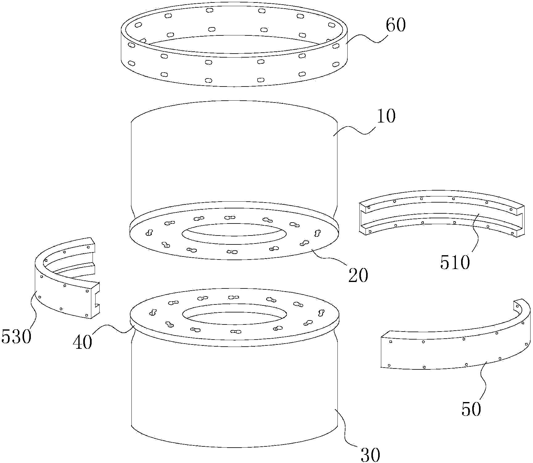
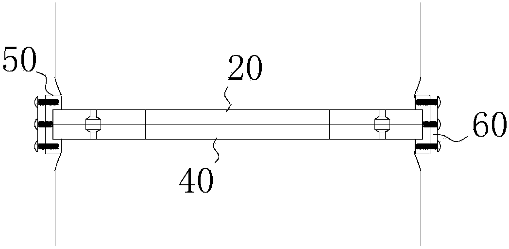
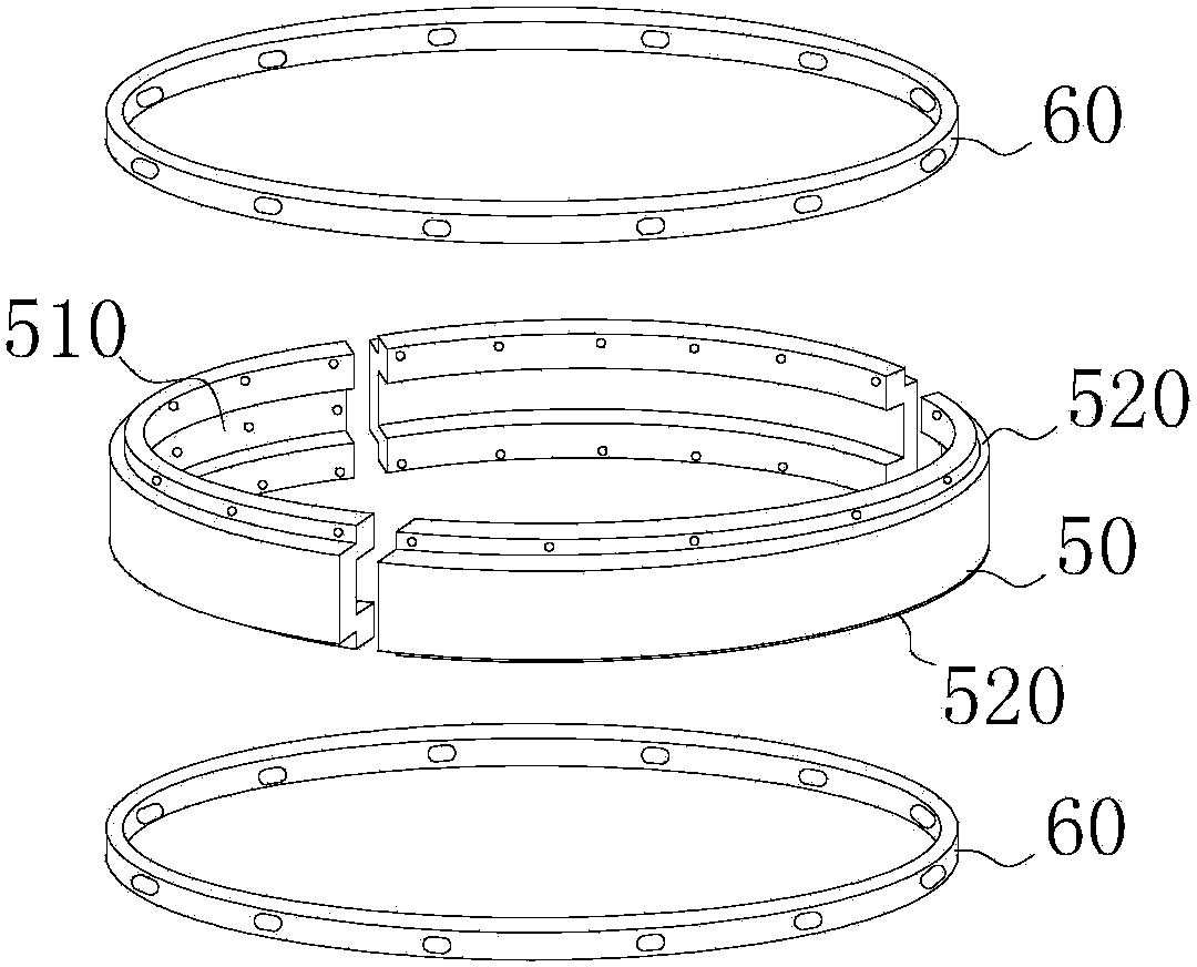
[0034] Please refer to Figures 1 to 2 . The pile connection structure is arranged between adjacent piles, and the piles used in engineering construction are formed by connecting the piles of multiple sections end to end. The pile connection structure includes an inner hoop, an outer hoop 60 arranged on the outer surface of the inner hoop 50 to tighten the inner hoop 50 , and a first end plate 20 and a second end plate 40 connected to each other. The first end plate 20 is integrally formed with the first pile 10, the second end plate 40 is also integrally formed with the second pile 30, the inner hoop 50, the outer sleeve, the first end plate 20 and the second The shape of the end plate 40 matches the section of the pile, so that the pile connection structure is suitable for any prefabricated piles with end plates, including prestressed concrete pipe...


PUM


Abstract

The invention discloses a pile connection structure, which comprises an inner hoop element, an outer sheathing hoop, a first end plate and a second end plate, wherein the outer sheathing hoop is arranged on the outer surface of the inner hoop element to tightly hoop the inner hoop element; the end surfaces of the first end plate and the second end plate are connected; the inner hoop element is provided with a first trough; a clamping element is formed by the first end plate and the second end plate and is arranged in the first trough. The pile connection structure disclosed by the invention has strong anti-shearing, anti-pulling and anti-bending capability and strong resistance to corrosion. Meanwhile, the use time of electric welding is reduced, the technical requirement on a construction worker is lowered, and the labor intensity of the worker is lightened.

Description

technical field [0001] The invention relates to the technical field of building components, in particular to a pile connection structure and piles. Background technique [0002] The pile connection structure currently on the market generally connects the upper end plate and the lower end plate by welding. This method of welding the upper end plate and the lower end plate has poor resistance to shearing, pulling, and bending, and at the same time, the weld is easily corroded because it is exposed. Furthermore, welded connections have high technical requirements for construction workers, and at the same time require high labor-intensive work for construction workers, resulting in low production efficiency. Contents of the invention [0003] Based on this, it is necessary to address the defects of the existing technology to provide a pile with strong shear resistance, pull resistance, bending resistance and corrosion resistance, while reducing the use of electric welding, re...

Claims


Application Information

Patent Timeline
Patent Type & Authority Applications(China)
IPC IPC(8): E02D5/24E02D5/58
Inventor 钟智谦钟肇鸿
Owner 钟智谦
Learn More