
Motor vehicle exhaust purifying device

A technology for exhaust gas purification devices and motor vehicles, which is applied in the direction of exhaust devices, noise reduction devices, machines/engines, etc., and can solve problems such as poor exhaust emissions, poor purification effects, and reducing agent pollution, so as to improve fuel economy and improve Purification efficiency and the effect of prolonging the contact time

Inactive Publication Date: 2014-04-30
赵金博
View PDF8 Cites 1 Cited by
  • Summary
  • Abstract
  • Description
  • Claims
  • Application Information

AI Technical Summary

Problems solved by technology

[0004] When the car works at low temperature for a long time, the three-way catalytic converter cannot be started, and the soot from the engine exhaust pipe will adhere to the surface of the catalyst, making it impossible to contact with CO and HC compounds. After a long time, the pores of the carrier will be blocked. affect its conversion efficiency
In addition, the exhaust emission is not smooth, and the power of the engine is difficult to exert, which is also the reason why many cars cannot run at high speed.
[0005] The tail gas of the existing tail gas purification device directly enters the liquid reducing agent, the contact time between the tail gas and the reducing agent is short, the reaction is not sufficient, the purification effect is poor, and the discharged tail gas still contains a large amount of CO and NO2, and the tail gas will reduce all the Reductant pollution, the service life of the reducing agent is very short, and the reducing agent needs to be replaced regularly to ensure the purification effect, resulting in very high cost of use, and it is inconvenient to replace the reducing agent

Method used


Image

  • Motor vehicle exhaust purifying device
  • Motor vehicle exhaust purifying device
  • Motor vehicle exhaust purifying device

Examples


Embodiment 1

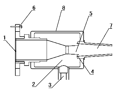
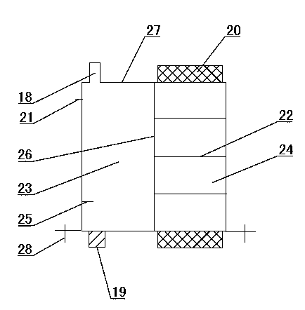
[0033] Reference Figure 1~4 , Motor vehicle exhaust purification device, including a purification injector, a purification room and a purification tank 27 that provides purification materials for the purification room. The engine exhaust pipe can be divided into three sections according to the direction of exhaust gas discharge. The purification injector and the purification room serve as the second Section is installed in the middle of the exhaust pipe, the output end of the purifying injector is connected to the first section of the engine exhaust pipe, the output end is connected to the clean room, the output end of the clean room is connected to the third section of the engine exhaust pipe, and the purification tank 27 is connected to the The adsorption chamber 2 of the ejector is connected to provide exhaust gas reductant and air for the purification room. The exhaust gas is sprayed into the purification room by a purification ejector. The exhaust gas reductant and air are...

Embodiment 2

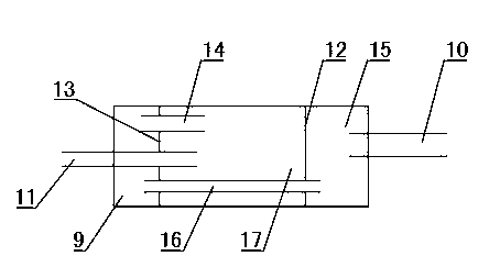
[0043] Reference Figure 5 The clean room is divided into the first clean chamber 15, the second clean chamber 17 and the third clean chamber 9 by the first porous partition 12 and the second porous partition 13, and the outlet of the air inlet passage 10 is located in the first In the second purification chamber 17, the inlet of the air outlet passage 11 is located in the first purification chamber 15. The first purification chamber 15 and the third purification chamber 9 are connected through the second inner cavity passage 14, and the third purification chamber 9 is The second purification chamber 17 is communicated through the first inner chamber passage 16, and the high-temperature exhaust gas enters the second purification chamber 17 from the intake passage 10 and mixes and burns with oxygen-enriched air to form a back pressure, and then most of the NO in the exhaust gas 2 It is reduced by the reducing agent in the first inner cavity channel 16 and the third purification ch...

Embodiment 3

[0045] Reference Image 6 The present invention can also divide the clean room by the first porous partition 12, the second porous partition 13 and the third porous partition 31 into the first purification chamber 15, the second purification chamber 17, and the third In the purification chamber 9 and the fourth purification chamber 29, the outlet of the air inlet passage 10 is located in the second purification chamber 17, and the inlet of the outlet passage 11 is located in the third purification chamber 9. The second purification chamber 17 and the fourth purification chamber The purification chamber 29 communicates through the first inner cavity passage 16, the fourth purification chamber 29 and the first purification chamber 15 communicate through the second inner chamber passage 14, and the first purification chamber 15 and the third purification chamber 9 pass through the The three inner chamber passages 30 are connected, and the high-temperature exhaust gas enters the sec...


PUM


Abstract

The invention discloses a motor vehicle exhaust purifying device, and belongs to the field of motor vehicle exhaust emission reduction. The motor vehicle exhaust purifying device comprises a purifying ejector, a purifying chamber and a purifying tank (27) for providing purifying matter for the purifying chamber. The purifying tank (27) is communicated with an adsorption cavity (2) of the purifying ejector, the input end of the purifying ejector is connected with an engine exhaust pipe, the output end of the purifying ejector is connected with a gas inlet channel (10) of the purifying chamber, the interior of the purifying chamber is divided by partition plates into a plurality of purifying cavities, the purifying cavities are communicated through inner cavity channels, and exhaust enters the purifying chamber through the gas inlet channel (10) and circularly flows in the purifying cavities to be purified to be emitted out through a gas outlet channel (11). The motor vehicle exhaust purifying device has the advantages that zero emission of exhaust harmful substance is achieved, the power of an engine is further improved, the combustion efficiency and the fuel economy are improved, and cost is low.

Description

Technical field [0001] A motor vehicle exhaust purification device belongs to the field of motor vehicle exhaust emission reduction. Background technique [0002] The three-way catalytic converter is a filtering device shaped like a "honeycomb coal". It is installed after the exhaust manifold of a motor vehicle engine. The three-way catalytic converter does not have the catalytic ability at room temperature. The catalyst must be heated to a certain temperature before it can be oxidized or reduced. Capacity, usually the reaction temperature of the three-way catalytic converter is 250~350℃, and the normal working temperature is generally 350~700℃. When the temperature exceeds 850~1000°C, the catalyst in the inner coating is likely to fall off and the carrier may break. [0003] The catalyst is very sensitive to elements such as sulfur, lead, phosphorus, and zinc. Sulfur and lead come from gasoline, while phosphorus and zinc come from lubricating oil. These four substances and the ox...

Claims


Application Information

Patent Timeline
IPC IPC(8): F01N3/08F01N3/04
Inventor 赵金博黄崇高赵华高述辕
Owner 赵金博
Learn More