
Equipment room floating structure

A machine room and equipment technology, applied in the field of equipment room floating structure, can solve the problems of long construction period, complicated construction process and high cost, and achieve the effects of short construction period, rich material selection and high compressive strength

Active Publication Date: 2016-04-13
XIAMEN JIADA OF ACOUSTIC TECH CO LTD
View PDF11 Cites 0 Cited by
  • Summary
  • Abstract
  • Description
  • Claims
  • Application Information

AI Technical Summary

Problems solved by technology

[0006] At present, the floating structure setting process of the equipment room is to set the reinforced concrete surface layer on the elastic cushion layer, the construction process is complicated, the construction period is long and the cost is high, including the decorative surface layer, the total height is ≥ 200mm

Method used


Image

  • Equipment room floating structure
  • Equipment room floating structure
  • Equipment room floating structure

Examples


Embodiment Construction

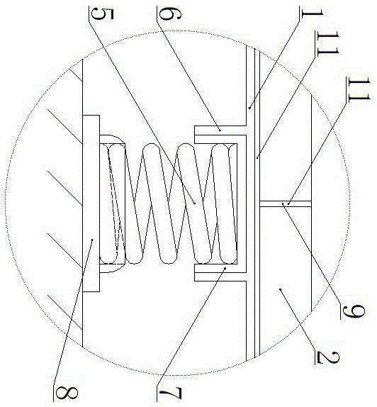
[0027] exist figure 1 , 2 In the shown embodiment, a floating structure of equipment room, elastic vibration isolation components, load-bearing steel plate structure (1), decorative quality panel (2) and the building structure facade (3) are arranged sequentially from bottom to top. ) and the elastic vibration isolation plate (4) between the load-bearing steel plate structure (1) and the decorative quality panel (2). The load-bearing steel plate structure (1) is composed of flat steel plates around corners to form a square frame, and the load-bearing steel plate structure (1) is arrayed with a plurality of elastic vibration-isolation components and fixed components. The elastic vibration isolation member is a steel spring (5), and the elastic vibration isolation member fixed member under the steel plate is a steel round tube (6), embedded with a rubber damping sleeve (7), and the outer diameter of the steel spring (5) is in line with the rubber The inner diameter of the damp...


PUM


Abstract

The invention discloses an equipment room floating structure. The equipment room floating structure is composed of elastic vibration-isolation components, force-bearing steel plate structures, a decoration quality face plate and an elastic vibration-isolation plate which are sequentially arranged from bottom to top, wherein the elastic vibration-isolation plate is arranged among a building structure vertical face, the force-bearing steel plate structures, and the decoration quality face plate. According to each force-bearing steel plate structure, a square frame is formed by folding corners of the periphery of a flat steel plate, and a plurality of elastic vibration-isolation component fixing components are arranged below each force-bearing steel plate structure in an array mode. The decoration quality face plate is composed of stone slabs or concrete slabs or slabs with the high density and decorating effect. Galvanization and anti-corrosive treatment are conducted on the force-bearing steel plate structures. The force-bearing steel plate structures are laid in a tightly abutting mode, folded corners of the force-bearing steel plate structures are in spot welding connection, gaps are filled with waterproof structural adhesive, and an integral force-bearing vibration-isolation structure is formed. The decoration quality surface plate adheres to the force-bearing steel plate structures through easy plaster. The equipment room floating structure has the advantages of being high in compressive strength and weather resistance, achieving simple construction processes, and being convenient to install.

Description

technical field [0001] The invention relates to a construction noise control technology, in particular to a floating structure of an equipment machine room which can solve the problem of floor vibration and sound transmission of power equipment. Background technique [0002] In modern buildings, the problem of poor floor impact sound is more prominent. The sound sources that produce impact sounds can be divided into two categories, one is machinery and equipment, and the other is human activities. After the sound source hits the contact parts, the vibration is transmitted to the building structure, and then transmitted to the room through the building structure, such as beams, floors, columns, and walls, forming sound wave radiation and generating noise. The characteristics of impact sound transmission are that the transmission distance is long and the influence range is large, and the listener feels that the sound comes from all directions. In residential buildings, the a...

Claims


Application Information

Patent Timeline
Patent Type & Authority Patents(China)
IPC IPC(8): E04B1/82
Inventor 何鹭凤蔡伟强杨锦勇林嘉祥
Owner XIAMEN JIADA OF ACOUSTIC TECH CO LTD
Learn More