
Intelligent power module and manufacturing method thereof

A technology of intelligent power module and manufacturing method, applied in semiconductor/solid-state device manufacturing, semiconductor/solid-state device components, semiconductor devices, etc., can solve the problem of increasing IPM manufacturing cost, manufacturing difficulty and pass rate, disconnection, and increasing flattening Equipment and other issues, to achieve the effect of controlling the difficulty of processing and the increase of processing costs, promoting miniaturization, and improving stability

Active Publication Date: 2014-03-12
MIDEA GRP CO LTD
View PDF7 Cites 12 Cited by
  • Summary
  • Abstract
  • Description
  • Claims
  • Application Information

AI Technical Summary

Problems solved by technology

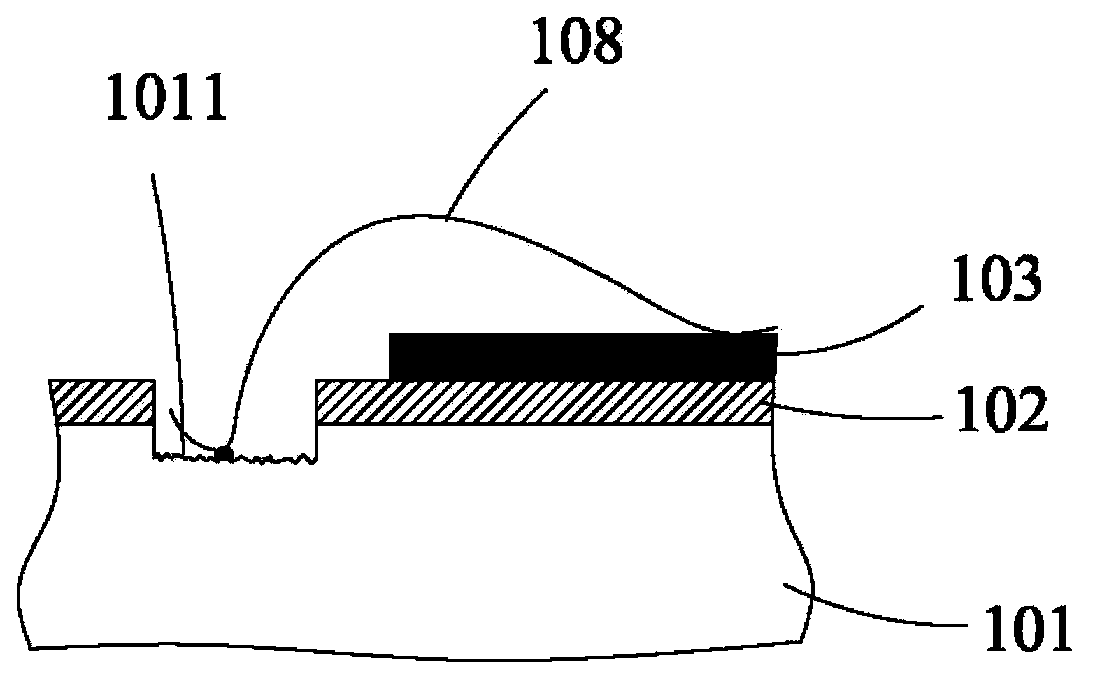
However, this method increases the flattening equipment, and has high requirements for the force of flattening, the speed of contact, and the accuracy of the flattened position. The design of this kind of equipment is difficult, the manufacturing cost is high, and the operation requirements for the operator It is also relatively high. Using this method to flatten the bottom will undoubtedly increase the manufacturing cost, manufacturing difficulty and pass rate of IPM.
Moreover, this method still uses the bonding force between the metal wire 108 and the metal substrate 101 to achieve fixation, and there is still a risk of wire breakage for long-term use under relatively harsh working conditions.

Method used


Image

  • Intelligent power module and manufacturing method thereof
  • Intelligent power module and manufacturing method thereof
  • Intelligent power module and manufacturing method thereof

Examples


Embodiment Construction

[0031] In order to make the object, technical solution and advantages of the present invention clearer, the present invention will be further described in detail below in conjunction with the accompanying drawings and embodiments. It should be understood that the specific embodiments described here are only used to explain the present invention, not to limit the present invention.

[0032] The specific realization of the present invention is described in detail below in conjunction with specific embodiment:

[0033] Reference attached Figure 5~8 , the smart power module includes a metal substrate 10, an insulating layer 11 is covered on one surface of the metal substrate 10, a circuit wiring 12 is arranged on the surface of the insulating layer 11, and a number of preset positions are arranged on the circuit wiring 12. The circuit element 13 is electrically connected to the circuit wiring 12 through a wire 14 . In addition, corresponding parts of the circuit wiring 12 are c...


PUM


Abstract

The invention belongs to the technical field of electronic devices and provides an intelligent power module and a manufacturing method thereof. The intelligent power module comprises a metal substrate, an insulating layer covering one surface of the metal substrate, a circuit wiring layer formed on the insulating layer, circuit elements which are configured at preset positions on the circuit wiring layer, and pins connected with the circuit wiring layer. The intelligent power module urther comprises a recessed hole which penetrates the insulating layer and extends to the metal substrate; the circuit wiring layer is connected with the bottom of the recessed hole through a metal wire; the recessed hole is filled with a cured conductive material; a tail portion of the metal wire, which is connected with the bottom of the recessed hole, is buried in the conductive material; and at least one surface of the metal substrate, which is provided with the circuit elements, is sealed. According to the intelligent power module of the invention, the recessed hole is filled with the conductive material, such that the connection of the metal wire and the bottom of the recessed hole can be realized by means of a bonding force of the metal wire and the recessed hole, and can be enhanced through the adhesive force of the conductive material, and therefore, reliable connection of the meal wire and the metal substrate can be realized, and the miniaturization of the module can be facilitated, and processing difficulty can be controlled, and cost can be decreased.

Description

technical field [0001] The invention belongs to the technical field of electronic devices, and in particular relates to an intelligent power module and a manufacturing method thereof. Background technique [0002] Intelligent Power Module (IPM) is a power drive product that combines power electronics and integrated circuit technology. IPM integrates power switching devices and high-voltage drive circuits, and has built-in fault detection circuits such as overvoltage, overcurrent and overheating. On the one hand, the IPM receives the control signal from the MCU to drive the subsequent circuits to work, and on the other hand, sends the system status detection signal back to the MCU. Compared with traditional discrete solutions, IPM has won an increasing market with its advantages of high integration and high reliability. It is especially suitable for frequency converters and various inverter power supplies for driving motors. An ideal power electronic device for electric tra...

Claims


Application Information

Patent Timeline
Patent Type & Authority Applications(China)
IPC IPC(8): H01L23/495H01L23/31H01L21/60H01L21/56
CPCH01L24/97H01L2224/48091H01L2224/48472H01L2224/8592H01L2924/19105H01L2924/19107H01L2924/181H01L2224/73265H01L2924/00014H01L2924/00H01L2924/00012
Inventor 冯宇翔黄祥钧
Owner MIDEA GRP CO LTD
Learn More