
Plug type current transformer

A current transformer, plug-in technology, applied in the field of plug-in current transformers, can solve the problems of small secondary output capacity, long power failure time, and failure to meet the use requirements

Inactive Publication Date: 2014-03-12
SHENYANG HUADE HIGH TECH ELECTRIC CO LTD
View PDF6 Cites 8 Cited by
  • Summary
  • Abstract
  • Description
  • Claims
  • Application Information

AI Technical Summary

Problems solved by technology

The current transformer directly connected to the primary cable is a low-voltage transformer, which does not need to withstand insulation stress and thermal stress. The outer shell is touchable and has high safety. The capacity is small, which is not compatible with the requirements of the State Grid. The State Grid requires a minimum secondary output capacity of 30 VA, but in actual engineering, the maximum secondary output capacity of this transformer can only reach 15 VA, so it cannot meet the requirements. Use requirements, and the connection between the primary cable and the main circuit needs to be untied when replacing, the system power failure time is longer, and the impact on the continuity of the power supply system is greater; the current transformer installed in the inflatable compartment of C-GIS, the secondary output Large capacity, small transformation ratio and large capacity can be realized, but this kind of transformer needs to withstand insulation stress and thermal stress, and is connected to the main circuit through flat terminal blocks. Power outages, especially when gas operations are required, can have an environmental impact if the inflatable compartment is filled with greenhouse gases such as SF6

Method used


Image

  • Plug type current transformer
  • Plug type current transformer
  • Plug type current transformer

Examples


specific Embodiment approach 1

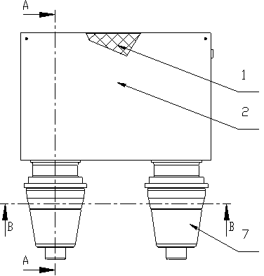
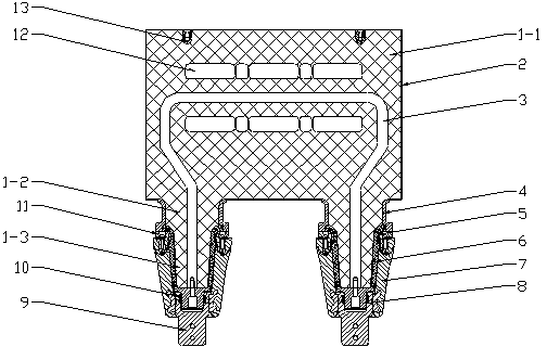
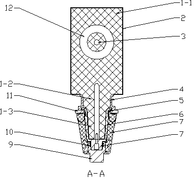
[0025] As shown in the accompanying drawings, the present invention includes a primary copper conductor 3 and a secondary winding 12, and consists of a rectangular casting 1-1, 2 cylindrical castings 1-2 and 2 conical castings 1-3 to form a ring The epoxy resin transformer casting body 1, that is, the epoxy resin transformer casting body 1 is made of 1 rectangular casting body 1-1, 2 cylindrical casting bodies 1-2 and 2 conical casting bodies 1-3. A whole epoxy resin casted by a vacuum casting mold. Conductive glue is sprayed on the outer surfaces of the 6 epoxy resins of the rectangular casting body 1-1, and threaded inserts are arranged inwardly, and are fixed and connected by countersunk screws with a thickness of 4 mm. The aluminum plate constitutes the grounded aluminum shell 2 of the transformer, the primary copper conductor 3 and the secondary winding 12 are installed in the epoxy resin transformer cast body 1, and the fixed flange 4 is installed outside the cylindrical ...

specific Embodiment approach 2

[0027] It is the same as the specific embodiment 1, the difference is that a hoisting insert 13 is provided on the epoxy resin transformer casting body 1 to facilitate hoisting of large current transformers, and when installing or dismounting the transformers, remove the fixing flange 4, the transformer can be disconnected from the bushing fixing plate 11 on the gas box and the inner cone bushing 7, and the connection between the hoisting equipment and the hoisting insert 13 can be used to realize the insertion and removal of the transformer, thereby reducing The power supply system does not need to open the inflatable compartment during the whole operation process due to the power outage time caused by the installation and replacement of the transformer, so there is no gas operation involved and no greenhouse gas emissions, thus avoiding the impact on the environment.


PUM


Abstract

The invention discloses a plug type current transformer overcoming the problem that the environment is influenced because the system power failure time is relatively long and a gas filled compartment is needed to be opened for carrying out gas operation when the current transformer is replaced in the prior art. The plug type current transformer is characterized in that a rectangular pouring body, two cylindrical pouring bodies and two conical pouring bodies form an epoxy resin transformer pouring body, wherein a grounded aluminum housing is arranged at the outer surface of the rectangular pouring body, fixed flanges are arranged outside the cylindrical pouring bodies, silicon rubber sleeves are arranged outside the conical pouring bodies, ground potential shielding layers are formed by spraying a conductive adhesive on a contact part of the silicon rubber sleeves and silicon rubber sleeve support rings, and the lower end of a primary copper conductor is fixedly connected with a conducive contact through a screw. The plug type current transformer has the beneficial effects that the plug type current transformer is directly plugged in an inner conical sleeve of a gas-insulated metal-enclosed switchgear to form a plug type connecting structure when being used, the system power failure time is short when the plug type current transformer is replaced, the gas operation is not involved, the safety, energy saving and environment friendliness are achieved, the disassembly, assembly and replacement speeds are high, and the housing can be touched.

Description

technical field [0001] The invention belongs to the technical field of current transformers, in particular to a plug-in current transformer for 72.5kV gas-insulated metal-enclosed switchgear. Background technique [0002] In the prior art, there are two types of current transformers used in gas-insulated metal-enclosed switchgear (C-GIS for short), one is directly connected to the primary cable, and the other is installed in the gas-filled barrier of C-GIS. room interior. The above two current transformers each have their own advantages and disadvantages. The current transformer directly connected to the primary cable is a low-voltage transformer, which does not need to withstand insulation stress and thermal stress. The outer shell is touchable and has high safety. The capacity is small, which is not compatible with the requirements of the State Grid. The State Grid requires a minimum secondary output capacity of 30 VA, but in actual engineering, the maximum secondary out...

Claims


Application Information

Patent Timeline
Patent Type & Authority Applications(China)
IPC IPC(8): H01F38/30H01F27/30H01F27/36H01F27/32H01F27/02H01F27/29
Inventor 蔡强涂佳明刘广斧贾延超
Owner SHENYANG HUADE HIGH TECH ELECTRIC CO LTD
Learn More