Coupling inductance double tube direct current converter with charge pump

A DC converter and coupled inductor technology, applied in the direction of converting DC power input to DC power output, converting equipment without intermediate conversion to AC, adjusting electrical variables, etc., can solve the problem of diode voltage stress, current stress, and inductor current. Ripple becomes larger and other problems, to achieve the effect of low voltage stress, natural turn-off solution, and low current stress

Inactive Publication Date: 2014-03-05
NANJING UNIV OF AERONAUTICS & ASTRONAUTICS
View PDF2 Cites 5 Cited by
  • Summary
  • Abstract
  • Description
  • Claims
  • Application Information

AI Technical Summary

Problems solved by technology

The boosting capability of the traditional Boost converter is very limited. As the gain increases, the duty cycle gradually increases, the inductor current ripple increases, and the required inductance also increases; and when applied to high output voltage applications, the power The voltage stress and current stress of the switch tube are large, and the conduction loss of the switch tube is large; the voltage stress of the diode on the output side is large, and the diode is hard to turn off, the reverse recovery problem and EMI problem are very serious, and the conversion efficiency is low

Method used


Image

  • Coupling inductance double tube direct current converter with charge pump
  • Coupling inductance double tube direct current converter with charge pump
  • Coupling inductance double tube direct current converter with charge pump

Examples


Embodiment Construction

[0029] Below in conjunction with accompanying drawing, the technical scheme of invention is described in detail:

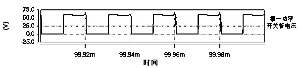
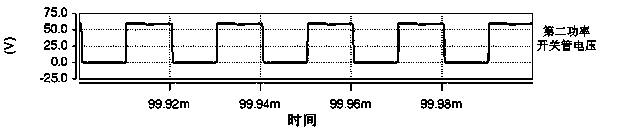
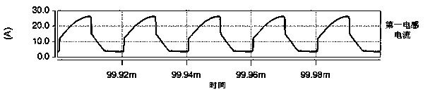
[0030] Such as figure 1 The shown coupled inductance dual-transistor DC converter with a charge pump includes a DC power supply, a first boost circuit, a second boost circuit, a first charge pump boost unit, a second charge pump boost unit, a first Clamping circuit, second clamping circuit, diode and load; the voltage output by the DC power supply is divided into two outputs, one of which is input to the first charge pump boosting unit after being initially boosted by the first boosting circuit, and then input to the first charge pump boosting unit after the first boosting circuit A charge pump boost unit is boosted twice and input to one end of the load through a diode; the first clamping circuit is used to clamp the first boost circuit, and the other circuit is initially boosted by the second boost circuit and then input to The second charge pump boost unit; a...


PUM


Abstract

The invention relates to a coupling inductance double tube direct current converter with a charge pump. The coupling inductance double tube direct current converter with the charge pump is characterized in that the coupling inductance double tube direct current converter comprises a direct-current power source, a first boosting circuit, a second boosting circuit, a first charge pump boosting unit, a second charge pump boosting unit, a first clamping circuit, a second clamping circuit, diodes and a load, wherein an output voltage of the direct-current power source is output through two paths, one path of the output voltage is input into the first charge pump boosting unit after undergoing primary boosting of the first boosting circuit and input to one end of the load through a diode circuit after undergoing secondary boosting of the first charge pump boosting unit, the first clamping circuit is used for clamping the first boosting circuit, the other path of the output voltage is input to the second charge pump boosting unit after undergoing primary boosting of the second boosting circuit and input to the other end of the load after undergoing secondary boosting of the second charge pump boosting unit, and the second clamping circuit is used for clamping the second boosting circuit. Voltage stress and current stress of a main power switch tube are small, the diodes are switched off naturally with zero current, the reverse recovery problem does not exist, and EMI of the circuits is small.

Description

technical field [0001] The invention relates to a coupled inductance double-tube DC converter with a charge pump, belonging to the field of power electronic converters. Background technique [0002] Under the dual pressure of energy shortage and environmental problems, new energy power generation has received extensive attention and research because of its cleanliness. In order to integrate a single photovoltaic cell and fuel cell into the grid, it is necessary to use a high-gain, high-efficiency DC converter to greatly improve the DC power generation. Voltage level. The boosting capability of the traditional Boost converter is very limited. As the gain increases, the duty cycle gradually increases, the inductor current ripple increases, and the required inductance also increases; and when applied to high output voltage applications, the power The voltage stress and current stress of the switch tube are large, and the conduction loss of the switch tube is large; the voltage...

Claims


Application Information

Patent Timeline
Patent Type & Authority Applications(China)
IPC IPC(8): H02M3/155H02M3/07
Inventor 汤雨王挺
Owner NANJING UNIV OF AERONAUTICS & ASTRONAUTICS
Why Eureka
Try Eureka