
Low-voltage high-current conducting bar fixing mode of electric furnace transformer

A technology of transformers and conductive bars, applied in the direction of transformers/inductor coils/windings/connections, etc., can solve the problems that affect the compression of the gasket 2, the heat of the screw 6 is severe, and the holes on both sides of the non-magnetic steel plate 5 cannot be opened through, etc. Achieve the effect of preventing excessive heating and reducing the probability of oil leakage

Active Publication Date: 2014-02-26
CHINT ELECTRIC
View PDF3 Cites 0 Cited by
  • Summary
  • Abstract
  • Description
  • Claims
  • Application Information

AI Technical Summary

Problems solved by technology

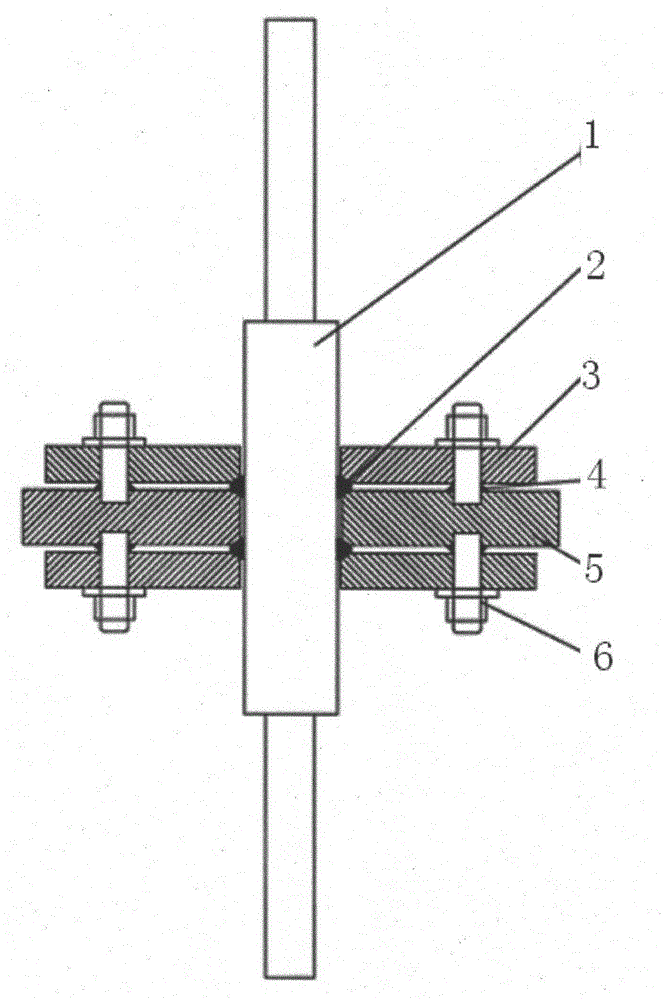
[0004] It has been proved by previous product operation and tests that this fixing method has shortcomings. The openings on both sides of the non-magnetic steel plate 5 cannot be penetrated. When welding the screw 6, it is difficult to grasp the verticality of the independent screws 6 on both sides. Generally, a transformer needs hundreds of them. Screw 6, some screws 6 will not be vertical enough, and the height of weld 4 at the bottom of screw 6 will affect the compression of gasket 2, and oil leakage will occur after a long time
When the transformer is running at full load, the ordinary steel screw 6 is in the electromagnetic field of tens of thousands of amperes and strong current, and the screw 6 is very hot, which will affect the safe operation of the transformer for a long time.

Method used


Image

  • Low-voltage high-current conducting bar fixing mode of electric furnace transformer
  • Low-voltage high-current conducting bar fixing mode of electric furnace transformer

Examples


Embodiment Construction

[0015] In order to make the present invention more comprehensible, a preferred embodiment is described in detail below with accompanying drawings.

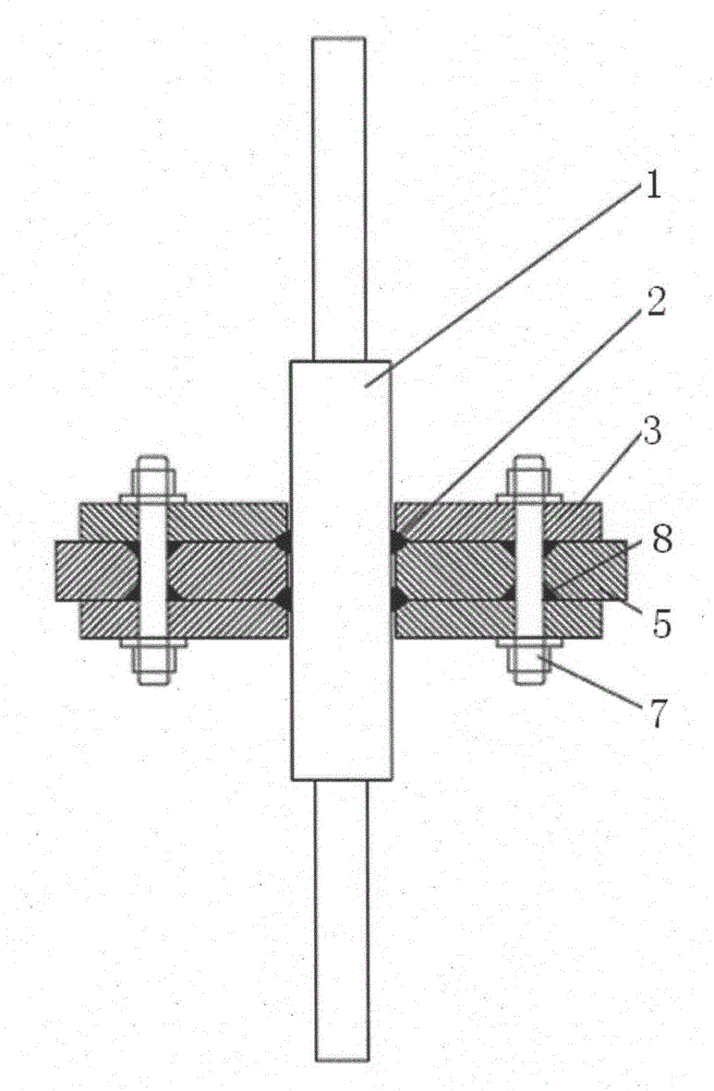
[0016] combine figure 2 , the invention provides a method for fixing the low-voltage and high-current conductive bars of electric furnace transformers, the steps of which are as follows:

[0017] Step 1. Fix the conductive bar 1 on the non-magnetic steel plate 5;

[0018] Step 2, opening through holes at the left and right ends of the non-magnetic steel plate 5, respectively chamfering grooves at the upper and lower ends of each through hole;

[0019] Step 3. Insert a non-magnetic screw rod 7 into each of the two through holes. The upper and lower ends of the non-magnetic screw rod 7 are respectively exposed to the upper and lower sides of the non-magnetic steel plate 5, and the beveled groove is used as the weld seam 8. Fix the non-magnetic screw rod 7 and the non-magnetic steel plate 5 by welding, and ensure that the upper an...


PUM


Abstract

The invention relates to a low-voltage high-current conducting bar fixing mode of an electric furnace transformer, and provides a coil head outgoing method for reducing partial discharge of the transformer. The mode is characterized by including the steps that (1) a conducting bar is fixed to a non-magnetic steel plate, (2) the left end and the right end of the non-magnetic steel plate are respectively provided with a through hole, and the upper end and the lower end of each through hole are respectively provided with a beveling groove in a chamfering mode, (3) two non-magnetic screw rods penetrate through the two through holes respectively, the upper end and the lower end of each non-magnetic screw rod are exposed out of the upper face and the lower face of the non-magnetic steel plate respectively, the non-magnetic screw rods and the non-magnetic steel plate are welded and fixed with the beveling grooves as welding seams, and after welding, smoothness of the upper face and the lower face of the non-magnetic steel plate is guaranteed; (4) the upper face and the lower face of the non-magnetic steel plate are respectively provided with a sealing pad, and the sealing pads are pressed with a pressing element. The low-voltage high-current conducting bar fixing mode has the advantages of reducing the oil leaking probability of the conductive bar after installation and preventing the fixing screw rods of the conducting bar from being exceedingly heated.

Description

technical field [0001] The invention relates to the design of a large-capacity, low-voltage, high-current electric arc furnace transformer, belonging to the technical field of electric arc furnace transformer design. Background technique [0002] For electric arc furnace transformers, the voltage on the low-voltage side is generally between tens and hundreds of volts. When the transformer reaches a certain capacity, the low-voltage current can reach tens of thousands of amps. Therefore, in the selection of bushings, ordinary bushings cannot meet the requirements. , then it is necessary to choose multiple high-current conductive bars to meet the requirements. [0003] For the installation of the conductive bar, it is the non-magnetic steel plate opening welding screw installation method. combine figure 1 , according to the drawing requirements of the conductive row manufacturer and the old design scheme of the original factory, holes are made on both sides of the non-magnet...

Claims


Application Information

Patent Timeline
Patent Type & Authority Applications(China)
IPC IPC(8): H01F27/29H01F27/30
Inventor 刘亚安祝志祥李灿
Owner CHINT ELECTRIC
Learn More