Reducer for concrete mixer

A technology of mixing main engine and reducer, which is applied in the direction of mechanical equipment, gear vibration/noise attenuation, transmission parts, etc., and can solve the problem of multi-section reducer, uneven clearance between planetary gear and internal gear tooth side, and reduced processing efficiency and other problems, to reduce the probability of reducer oil leakage, improve stability and reliability, and improve processing efficiency

Active Publication Date: 2017-02-15
XUZHOU XCMG CONSTR MACHINERY CO LTD BUILDING MACHINERY
View PDF6 Cites 0 Cited by
  • Summary
  • Abstract
  • Description
  • Claims
  • Application Information

AI Technical Summary

Problems solved by technology

[0003] exist figure 1 In the structure of the reducer shown, the planet carrier adopts the form of fixed support at both ends, which requires high machining accuracy for the reducer housing. If the housing is not processed properly, it is easy to cause the backlash between the planetary gear and the internal gear. Uneven, which in turn will lead to uneven load transmission of each planetary gear, causing premature wear of the planetary gear with small backlash, reducing the stability and reliability of the transmission
In addition, since both ends of the planet carrier are supported by bearings, the coaxiality of the two bearing holes is required to be high, which reduces the processing efficiency
[0004] At the same time, the inside of the reducer requires a large space, so it occupies more shells, resulting in more split surfaces of the reducer, which also increases the probability of gear oil leakage

Method used


Image

  • Reducer for concrete mixer
  • Reducer for concrete mixer
  • Reducer for concrete mixer

Examples


Embodiment Construction

[0017] The technical solutions of the present invention will be described in further detail below with reference to the accompanying drawings and embodiments.

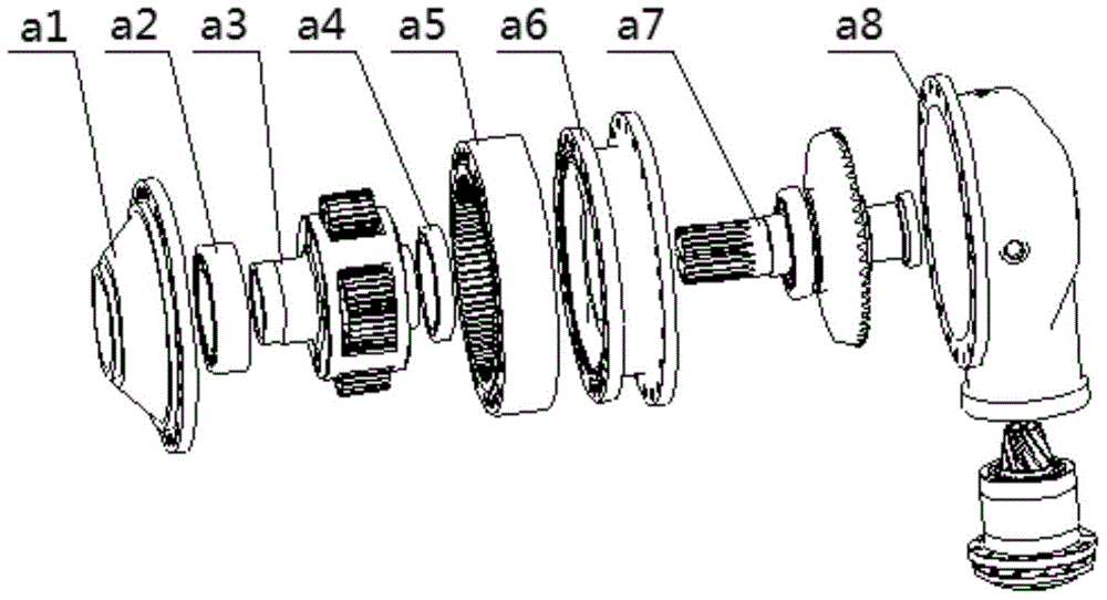
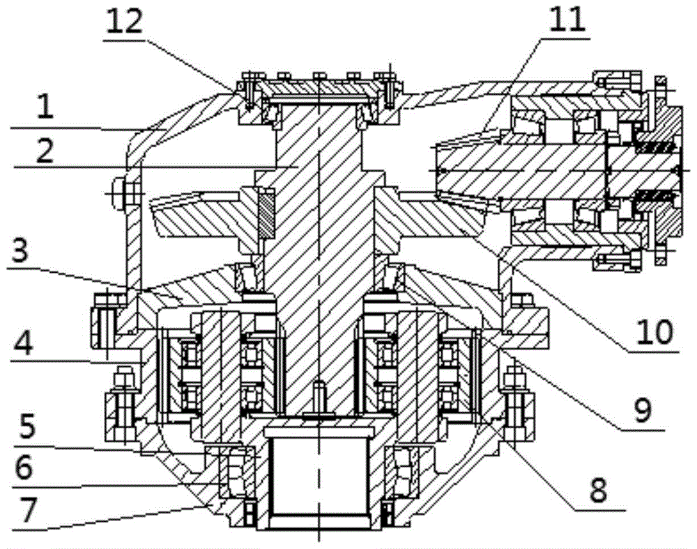
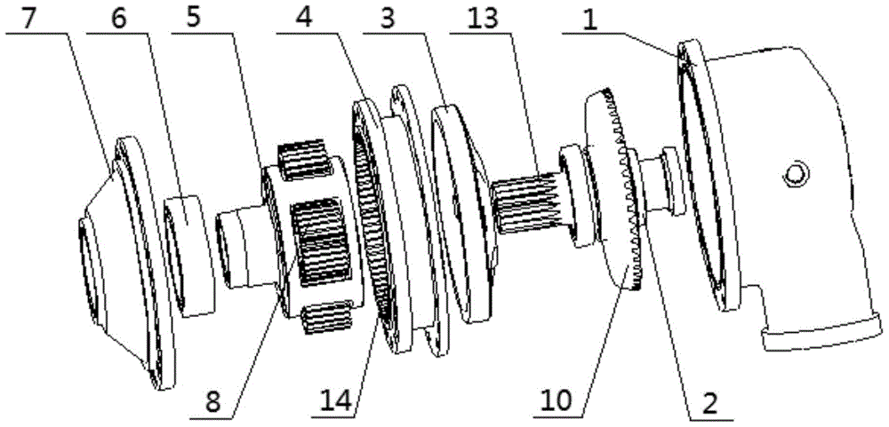
[0018] like figure 2 Shown is a schematic cross-sectional structure diagram of an embodiment of the speed reducer for the concrete mixing main engine of the present invention. combine image 3 , 4 As shown in the exploded diagram of the internal structure, the reducer for the concrete mixing main engine in this embodiment: includes the upper casing 1, the lower casing 7, the planetary carrier assembly 5, the internal gear 4 and the gear shaft 2, and one end of the gear shaft 2 is along the Tooth 13 is provided in the circumferential direction, and extends into the planetary carrier assembly 5, and meshes with each planetary gear 8 in the planetary carrier assembly 5, and each planetary gear 8 of the planetary carrier assembly 5 meshes with the internal gear 4, and the planetary carrier assembly 5 is arranged on Bet...


PUM


Abstract

The invention relates to a speed reducer for a concrete mixing main machine. The speed reducer comprises an upper casing, a lower casing, a planet carrier assembly, an inner gear and a gear shaft, wherein teeth are arranged at one end of the gear shaft in the peripheral direction, the gear shaft extends into the planet carrier assembly and meshed with all planet gears in the planet carrier assembly, the planet gears of the planet carrier assembly are meshed with the inner gear, the planet carrier assembly is arranged between the upper casing and the lower casing, and the planet carrier assembly is of a single-end floating type supporting structure to achieve transmission. Due to the facts that the planet carrier assembly is of the single-end floating type supporting structure to achieve transmission and the two ends are not supported by a bearing, the coaxiality requirements for bearing holes needn't to be taken into consideration. Thus, the processing efficiency is improved. Meanwhile, the single-end floating type supporting structure can balance load between all planet gears in the planet carrier assembly, the gear side gap between the planet gears and the inner gear can be adjusted by self according to radial stress on the planet gears, the rotation noise is reduced, and the stability and the reliability of transmission are improved.

Description

technical field [0001] The invention relates to the field of engineering machinery, in particular to a reducer for a concrete mixing main engine. Background technique [0002] Concrete mixing main engine is a kind of construction machinery equipment that mixes cement, gravel, sand, etc. into concrete. The reducer used in it is mainly composed of shell, planetary frame assembly, planetary frame support bearing and screw umbrella assembly. like figure 1 Shown is an exploded schematic diagram of the internal structure of an existing reducer. The speed reducer includes three sections of housing, which are the upper housing a8, the middle housing a6 and the lower housing a1 respectively. The gear shaft a7 is installed in the upper housing a8, and the gear shaft a7 is connected by the upper housing a8 and the middle housing a6. The two axial ends of the planetary carrier assembly a3 are respectively supported by the self-aligning roller bearing a2 and the deep groove ball bearin...

Claims


Application Information

Patent Timeline
Patent Type & Authority Patents(China)
IPC IPC(8): F16H1/28F16H57/021
CPCF16H1/28F16H57/0006F16H57/021F16H2057/02086F16H2057/02095
Inventor 徐怀玉汤传彬樊学勇张承信王源黄元王松
Owner XUZHOU XCMG CONSTR MACHINERY CO LTD BUILDING MACHINERY
Why Eureka
Try Eureka