
Method and system for simulating flow of fluid around a body

a fluid flow and fluid simulation technology, applied in the field of methods and systems for simulating fluid flow around the body, can solve the problems of complex process for generating meshes, complex application of unstructured mesh solvers, and difficult to conform to complex geometry, etc., to achieve easy parallel computation, reduce computational load of each cube, and reduce the effect of complexity

Inactive Publication Date: 2011-04-05
HONDA MOTOR CO LTD
View PDF4 Cites 22 Cited by
  • Summary
  • Abstract
  • Description
  • Claims
  • Application Information

AI Technical Summary

Benefits of technology

The present invention provides a simulation method and system for flow of fluid around a body using cubes with a uniform number of cells. The target domain of simulation is divided into small units called cubes, and each cube is computed independently. The data is exchanged between adjacent cubes after each computational step. The system can adapt to complex geometry and high resolution. The method and system are easy to use and distribute the computational load evenly, making it suitable for solution adaptive grid control and high resolution scheme.

Problems solved by technology

Structured mesh solver is very good for application in high resolution scheme, but a procedure for generating mesh is complicated.
Further, an application of structured mesh solver is subject to some types of constraints in conforming to complex geometry and in solution adaptive grid control (in which grid shapes are adapted to solutions).
However, an application of unstructured mesh solver is subject to some types of constraints in high resolution scheme and in mesh generation.
Cartesian mesh solver is very good at mesh generation, but not good for conforming to complex geometry and for application in solution adaptive grid control.
Further, an application of Cartesian mesh solver is subject to some types of constraints in high resolution scheme.
Thus there has not been a method for simulating flow of fluid around a body that is good for conforming to complex geometry, application in solution adaptive grid control, application in high resolution scheme and mesh generation.

Method used


Image

  • Method and system for simulating flow of fluid around a body
  • Method and system for simulating flow of fluid around a body
  • Method and system for simulating flow of fluid around a body

Examples


Embodiment Construction

[0033]The basic idea of the present invention is to apply a simple Cartesian mesh in an attempt to develop a fast, low-storage method for time-accurate computation of the Navier-Stokes equations for a complex geometry.

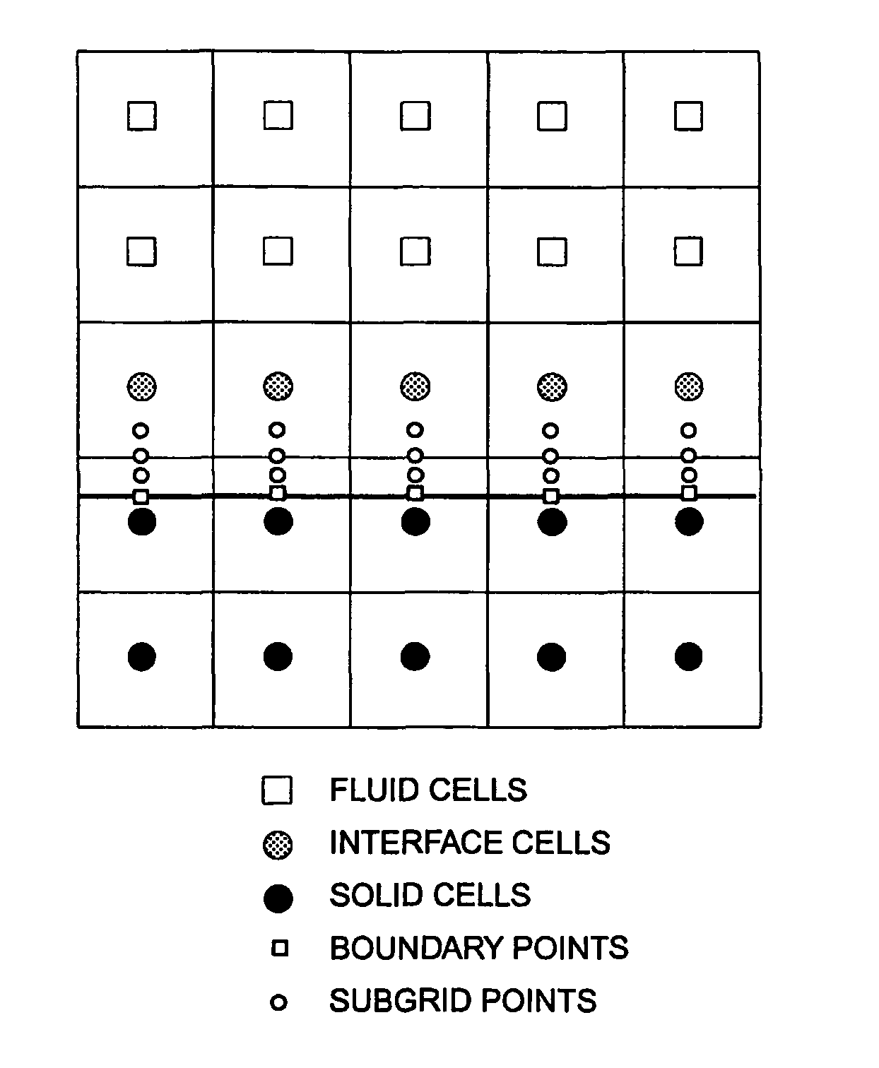
[0034]In the method according to the invention, the computational domain is divided into a number of tree data structured sub-domains. The sub-domains are named cubes. A size of each cube is determined by adapting to the geometry of the body and the local characteristic flow length. A uniformly divided Cartesian mesh is generated in each cube. Elements of the Cartesian mesh are called cells. All cubes contain the same number of cells, so that the local computational resolution is determined by the cube size. The same mesh density among all cubes simplifies the parallel computation, because all cubes have substantially the same computational load.

[0035]FIG. 3(a) shows cubes generated around the body. FIG. 3(b) is a partially enlarged drawing of FIG. 3(a).

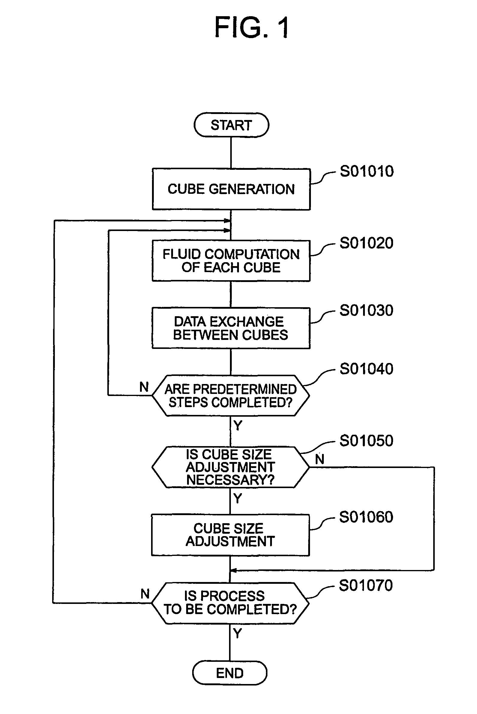
[0036]FIG. 1 is...


PUM

PropertyMeasurementUnit
Reynolds numberaaaaaaaaaa
angle of attackaaaaaaaaaa
sizesaaaaaaaaaa

Abstract

A simulation method for flow of fluid around a body, according to the present invention, comprising dividing a target domain of simulation into a plurality of computational unit domains named cubes, generating an uniform number of Cartesian mesh elements named cells, in each of the cubes, performing computation in the cubes in each computational step, and exchanging data between adjacent cubes after completion of each computational step. In dividing the target domain of simulation into cubes, division is repeated while a ratio between adjacent cube sizes is maintained in a certain range until cubes including a boundary between the body and the fluid, is small enough to obtain a desired resolution so that sizes of the cubes are appropriately determined according to a shape of the body.

Description

CROSS-REFERENCE TO RELATED APPLICATIONS[0001]This application claims priority of U.S. provisional application No. 60 / 878,413 filed on Jan. 4, 2007.FIELD OF THE INVENTION[0002]The present invention relates to a method and a system for simulating flow of fluid around a body.BACKGROUND OF THE INVENTION[0003]Solutions for analyzing flow of fluid around a body by computational fluid dynamics (CFD) can be classified into structured mesh solver, unstructured mesh solver and Cartesian mesh solver (as shown in the second paragraph and FIGS. 1 to 3 of JP2005-78416A).[0004]Table 1 is a table in which characteristics of structured mesh solver, unstructured mesh solver and Cartesian mesh solver are summarized.[0005]TABLE 1StructuredUnstructuredCartesianMesh SolverMesh SolverMesh SolverConforming to ComplexLimitedGoodBadGeometrySolution Adaptive GridLimitedVery GoodBadControlHigh-resolution SchemeVery GoodLimitedLimited2nd Order2nd Order2nd OrderEasy Mesh GenerationBadLimitedVery GoodLarge Scale ...

Claims


Application Information

Patent Timeline
Patent Type & Authority Patents(United States)
IPC IPC(8): G06F7/60G06G7/48G06F17/10G06G7/50G06G7/57G01N11/00G01F23/00
CPCG06F17/5009G06F2217/16G06F30/20G06F2111/10
Inventor KAMATSUCHI, TOSHIHIRO
Owner HONDA MOTOR CO LTD
Learn More