
Additive manufacturing and subtractive manufacturing combination based integrated forming equipment for bionic structures

A forming equipment and bionic technology, applied in the direction of prosthesis, medical science, stent, etc., can solve the problems of low forming efficiency, non-replacement, large limitations, etc., and achieve the effect of improving forming efficiency, avoiding processing, and improving forming accuracy

Inactive Publication Date: 2014-02-26
TSINGHUA UNIV
View PDF4 Cites 28 Cited by
  • Summary
  • Abstract
  • Description
  • Claims
  • Application Information

AI Technical Summary

Problems solved by technology

[0009] ①The fixed injection device can only use the nozzle for processing and size control, and the surface and inner cavity of the molded body are rough, requiring post-processing such as grinding, drilling, milling, etc., and the molding efficiency is low;
[0010] ②The forming table can only rely on the three-dimensional motion device to move, and the position parameters are controlled by the X-axis and Y-axis perpendicular to each other when processing circular section and ring section materials, and the accuracy needs to be improved;
[0011] ③The fixed nozzles are all screw extrusion type and cannot be replaced. There are structural disadvantages during processing, and it is impossible to finely control the amount of extruded material;
[0012] ④ There is only one nozzle for each nozzle of the injection device, which has great limitations in multi-directional forming
[0013] ⑤ There is no heat treatment before the raw material is extruded from the nozzle, and the difficulty of processing and molding will vary with the melting point of the material

Method used


Image

  • Additive manufacturing and subtractive manufacturing combination based integrated forming equipment for bionic structures
  • Additive manufacturing and subtractive manufacturing combination based integrated forming equipment for bionic structures
  • Additive manufacturing and subtractive manufacturing combination based integrated forming equipment for bionic structures

Examples


Embodiment 1

[0052] Example 1: Forming of organ precursors: 1) Before forming the three-dimensional structure, use three-dimensional modeling software to establish a three-dimensional model, use layering processing software to layer the model, obtain the numerical control code for forming, and convert the layer file and processing parameters Input the computer control software; 2) Select the materials for the experiment. In this embodiment, the synthetic polymer polyurethane (PU) / tetraethylene glycol (Tetraglycol) solution is used as the peripheral scaffold material of the vascular system, and a certain proportion of fat stem cells and adult cells are selected. Cells, using phosphate buffered solution (PBS) containing endothelial cell growth factor (PBS) or gelatin / fibrinogen mixed solution as raw materials, prepared according to an appropriate ratio, and made into molding materials for later use; Sterilization; 4) Add different forming materials into each barrel of the raw material box of ...

Embodiment 2

[0053] Example 2: Processing and molding of smooth round tubes filled with titanium alloy hard tissue: 1) Before forming, use 3D modeling software to build a 3D model, use layered processing software to layer the model, and obtain the NC code for forming, select For the processing plan of circular cross-section parts, set the rotation parameters of the forming table, and input the layer file and processing parameters into the computer control software; The temperature heats the barrel; 3) Set the horizontal offset between the nozzle and the center position of the forming table, and the spraying of the nozzle starts after the forming table starts to rotate; 4) After the main body is formed, it is tightened by the table holding mechanism, and the subtractive manufacturing mechanism adopts polishing 5) The forming table is deflected by 30°, and the subtractive manufacturing mechanism is sequentially replaced with a drill bit and a tap to drill oblique holes on the outer surface of...

Embodiment 3

[0054]Example 3: Forming of bone tissue repair materials: 1) Before forming, use 3D modeling software to establish a 3D model, use layering processing software to layer the model, obtain the NC code for forming, and input the layer file and processing parameters Computer control software; 2) Select polylactic acid and polyglycolic acid copolymer (PLGA) and calcium phosphate, degradable calcium phosphate bone cement and phosphorylated chitosan as experimental materials, dissolve PLGA in 1.4-dioxane solution and Mix the calcium phosphate powder evenly, put it into the cylinder with the degraded calcium phosphate bone cement and phosphorylated chitosan slurry before curing, turn on and preheat to the ejection condition; 3) Set the position of each nozzle and the forming table before starting processing Use the control and data processing system to center (knife), start the temperature control cooling device, make the temperature in the equipment drop to a certain value and maintai...


PUM


Abstract

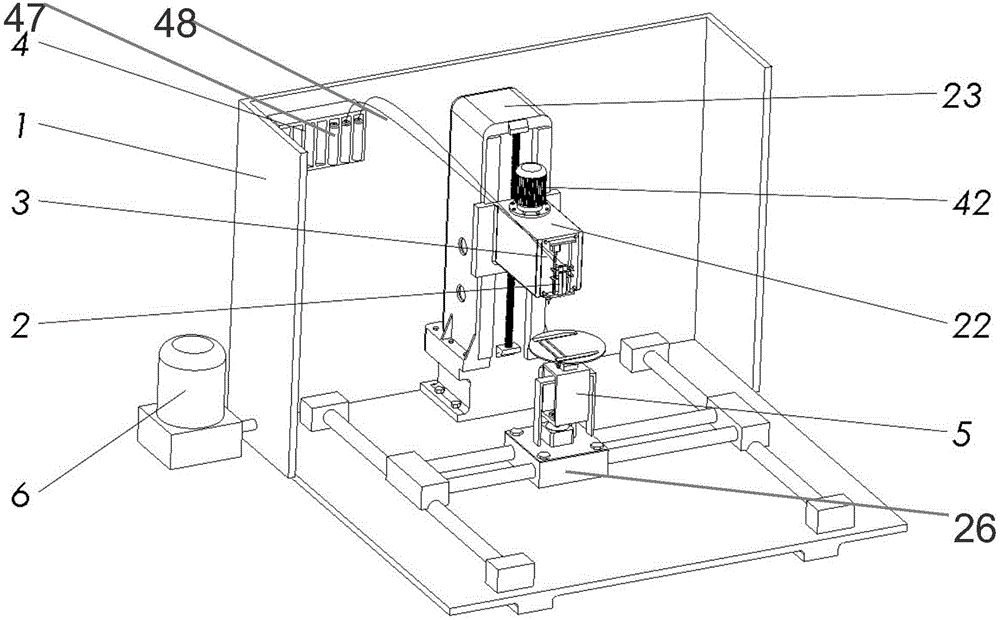
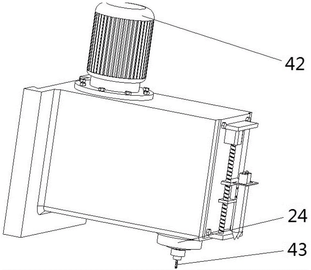
The invention discloses additive manufacturing and subtractive manufacturing combination based integrated forming equipment for bionic structures and belongs to the technical field of tissue engineering. The additive manufacturing and subtractive manufacturing combination based integrated forming equipment mainly comprises a case, a support, a multi-nozzle spraying device, a subtractive manufacturing mechanism, a forming table, a temperature control and cooling device, a three-dimension motion mechanism, a feed box and a control system. A composite processing device utilizing combination of nozzle extrusion molding and subtractive manufacturing is adopted; through vertical moving of the multi-nozzle spraying device and rotary deflection motion of the forming table, the nozzles can compete extrusion molding individually; further, by subtractive manufacturing means such as milling, drilling, boring, grinding and tapping, efficient stacking integrated forming and after-processing of the bionic structures under cooperation of multi-nozzle molding and subtractive manufacturing finishing machining are realized.

Description

technical field [0001] The invention belongs to the technical field of tissue engineering, and in particular relates to the design of an integrated forming device of a bionic structure combining additive and subtractive manufacturing. Background technique [0002] Rapid prototyping technology in additive manufacturing is a popular interdisciplinary subject at present. Its main feature that is different from the traditional manufacturing method is the incremental forming of layer-by-layer accumulation. Rapid prototyping technology has a wide range of applications, such as manufacturing, medicine, biology, architecture, art, and industrial design. [0003] The rapid prototyping technology that came out in the late 1980s, as an important member of advanced manufacturing technology, gradually entered the field of tissue engineering forming. train of thought. Rapid prototyping technology is most rapidly applied in the manufacture of biological scaffolds and molds in tissue eng...

Claims


Application Information

Patent Timeline
IPC IPC(8): A61F2/82A61F2/02A61F2/28A61C13/08B05B15/10B05B13/02
Inventor 王小红王镓垠
Owner TSINGHUA UNIV
Learn More